Brake and Turn Signal Gear

a technology of signal gear and brake, applied in the field of signal gear, can solve the problems of difficult installation, inconvenient use, inaccurate, etc., and achieve the effect of convenient installation

Inactive Publication Date: 2015-04-23
LAU KOON HANG
View PDF3 Cites 23 Cited by
  • Summary
  • Abstract
  • Description
  • Claims
  • Application Information

AI Technical Summary

Benefits of technology

[0003]The present invention relates to a signal gear, in particular, to a brake and turn signal gear (BTG) for bicycle. The signal gear of the present invention is mainly used when cycling.

Problems solved by technology

However, most of the conventional gears for cyclists capable of giving these signals are either bulky, difficult to install, inefficient, inaccurate, or non-user friendly.
However, the sensing mechanism depending on pressure sensor is easy to make wrong signals if the cyclists accidentally apply pressure through their finger where the pressure sensor is incorporated and the pressure value is over the predetermined threshold.
Otherwise, normal cyclists may be at risks of giving wrong signals to the other users on the paths, streets or roads by using the signal glove provided in CN203121096U.
An on / off button incorporated into the index finger section of this glove is used to control the power on / off of the glove, which is not user-friendly when a quick turn motion of the bicycle is required.
However, the glove provided in this UK patent is bulky and non-user friendly because at least two fingers need to be in contact with each other in order to turn on the signal lamp.
It also does not favor giving brake signal if the cyclist needs to stop the bicycle by holding the brake handle of the handle bar with the forefinger and thumb.
Although the position of the pressure switch is designed to avoid accidental activation, the position to where the pressure is applied is limited to the underside of the brake.
If the hand brake of the bicycle is not held in a position parallel to the handlebar, this activation mechanism of the light signal will not be applicable.

Method used


Image

  • Brake and Turn Signal Gear
  • Brake and Turn Signal Gear
  • Brake and Turn Signal Gear

Examples


example 1

[0030]In FIG. 3A, the brake signal is off because the “switch” is opened by virtue of two points of electrical conductive material on two separate fingers of the BTG which are not in contact with the corresponding conductive material on the hand brake. The open circuit for the situation in FIG. 3A is illustrated in FIG. 3B. When the two points of electrical conductive material on two separate fingers of the BTG are in contact with the corresponding conductive material on the hand brake, as shown in FIG. 3C, the circuit of the brake signal which is a red light signal is closed, as shown in the schematic diagram of FIG. 3D. In this situation, the red light is on to notify other road users that the bicycle is intended to either stop or slow down. Although the two points of electrical conductive material are attached onto the index and middle fingers respectively in this example, it should be understood that the conductive material is not limited to be attached to these two fingers. The...

example 2

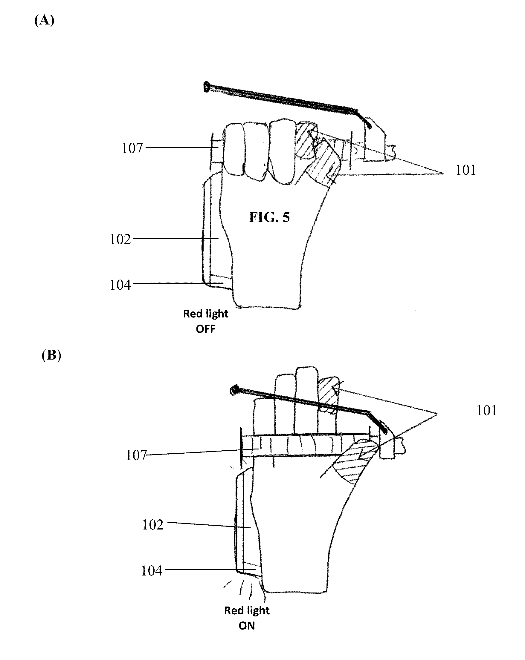
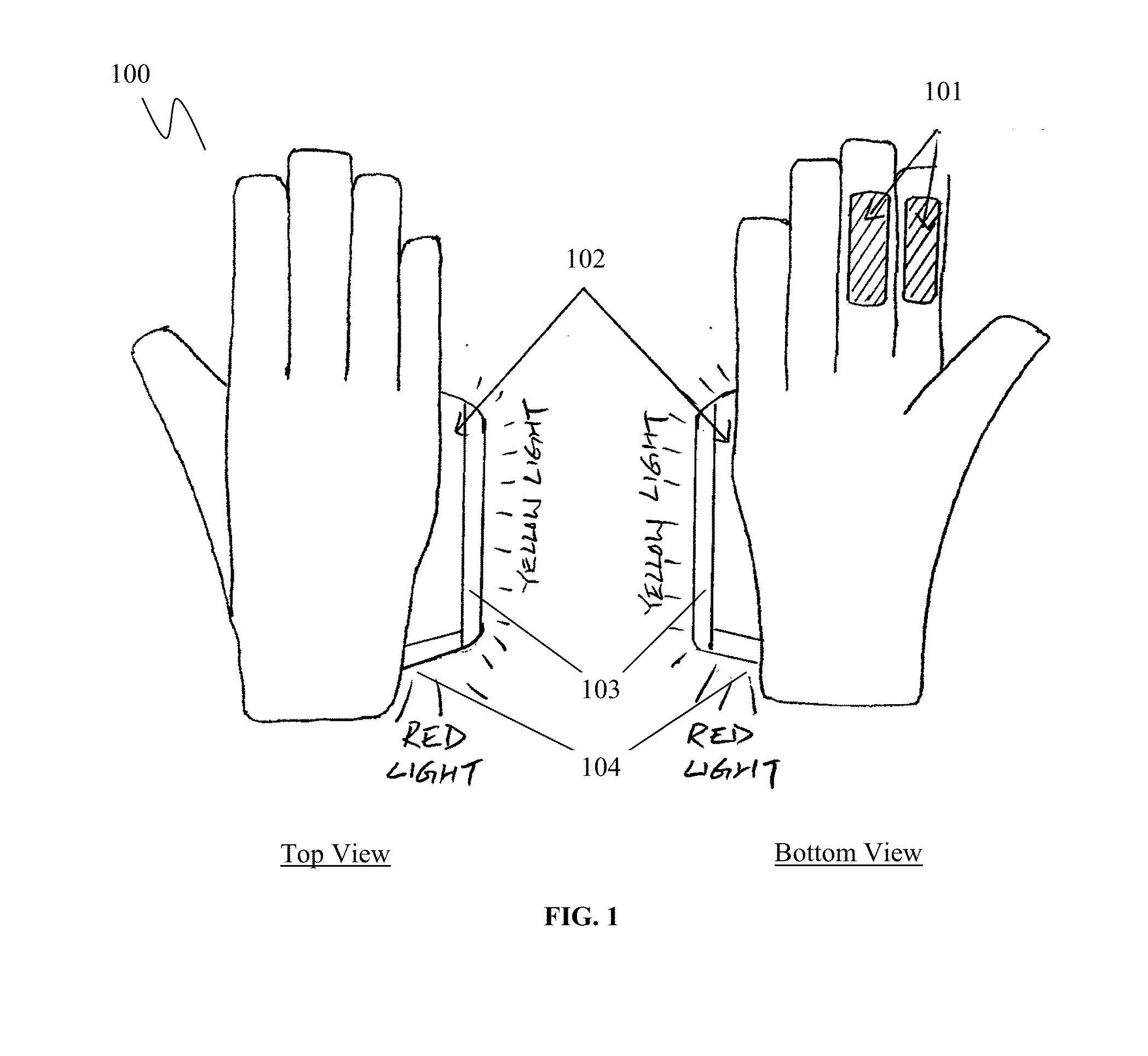
[0031]In FIG. 4, the conductive material covers the thumb and index finger of the BTG. The signaling component of the BTG also includes a turn signal (103) and brake signal (104). In this example, when the conductive material on the index finger is in contact with the conductive material on the thumb, the brake signal is off (FIG. 5A). On the other hand, when they are not in contact, brake signal is on (FIG. 5B). A relay switch circuit with normally-closed (NC) contacts is incorporated into the BTG. The relay switch circuit controls the on / off of the signal component, so that when the “switch” circuit is closed, the signal component is off. When the “switch” circuit is opened, the signal component is on. In this example, when the cyclist holds the handle bar 107 with his / her index finger touching the thumb, the conductive material 101 on those fingers will be in contact, the brake light 104 will be turned off (FIG. 5A). When the cyclist prepares to slow down or brake, he / she can rel...

example 3

[0032]FIG. 6 illustrates that the brake light 104 is operated by two pieces of conductive material 101 that are attached to bottom side of both index and middle finger. When the cyclist holds the conductive handle bar 107 with both index and middle fingers, the brake light 104 is turned off (FIG. 7A). It is controlled by the relay switch circuit with normally-closed (NC) contacts inside the battery compartment 102. When the cyclist prepares to slow down or to brake, he / she may release their fingers from the conductive handle bar 107, or then further holding the non-conductive hand brake with their fingers. In these situations, the conductive material between the index finger and middle finger are not in contact, and as such the brake light 104 is turned on (FIG. 7B).


PUM


Abstract

The present invention provides a signal gear for cyclist to give brake and turn signals to other road users while the cyclist has full control of the handle bar and brake. The signal gear of the present invention is preferably a glove with finger portions. Control and activation of the turn and / or brake signals is mainly by using electrical conductive nature of the signal glove as a switch of the signaling component which is either incorporated with the glove or with the vehicle (e.g. bicycle). The signaling component can emit turn / brake light signal or transmit an activation signal to a light emitting device to give turn / brake light signal. The turn and brake light signals are in yellow and red color, respectively.

Description

CROSS REFERENCE TO RELATED APPLICATION[0001]Pursuant to 35 U.S.C. §119(e), this is a non-provisional patent application which claims benefit from US provisional patent application Ser. No. 61 / 892,478 filed Oct. 18, 2013 and U.S. provisional patent application Ser. No. 62 / 004,881 filed May 29, 2014, and the disclosure of which are incorporated herein by reference in their entirety.COPYRIGHT NOTICE[0002]A portion of the disclosure of this patent document contains material, which is subject to copyright protection. The copyright owner has no objection to the facsimile reproduction by anyone of the patent document or the patent disclosure, as it appears in the Patent and Trademark Office patent file or records, but otherwise reserves all copyright rights whatsoever.TECHNICAL FIELD[0003]The present invention relates to a signal gear, in particular, to a brake and turn signal gear (BTG) for bicycle. The signal gear of the present invention is mainly used when cycling.BACKGROUND OF THE INV...

Claims


Application Information

Patent Timeline
Patent Type & Authority Applications(United States)
IPC IPC(8): A41D19/00A41D13/005B62J6/16B62J6/00B62J6/04
CPCA41D19/0024B62J6/005B62J6/003B62J2006/006B62J6/16A41D13/0051B62J2006/008B62J6/04A41D19/0157B60Q1/2673B60Q2900/30B62J6/015B62J6/045B62J6/056B62J6/165B62J6/057
Inventor LAU, KOON HANG
Owner LAU KOON HANG
Why Eureka
Try Eureka