Cyclonic separator having a shroud

a cyclonic separator and shroud technology, which is applied in the direction of vortex flow apparatus, filter means, separation processes, etc., can solve the problems of affecting the flow of cyclone air, affecting the stability of the cyclone chamber, and the mesh can look unsightly to a user, so as to improve the yield point, improve the service life, and improve the flexibility of the flexible portion

Inactive Publication Date: 2015-04-23
DYSON TECH LTD
View PDF0 Cites 12 Cited by
  • Summary
  • Abstract
  • Description
  • Claims
  • Application Information

AI Technical Summary

Benefits of technology

[0005]As a result, an improved solution for tensioning the mesh of a shroud is provided. Specifically, when assembled, the projecting member abuts the inner flange without forming any undesirable pockets that can collect dirt. In addition, the flexible portion that allows the mesh to be tensioned is provided on the shroud itself, rather than on the inner wall of the cyclonic separator. This then makes it easier to repair the cyclonic separator should the flexible portion no longer provide the required tension. In this instance, only the shroud will need to be replaced, rather than the entire inner wall. Furthermore, it may be easier to make the flexible portion more robust when part of the shroud (and therefore hidden from view) rather than the inner wall, such that it has a much higher yield point.
[0006]The flexible portions may comprise tabs formed between cuts in the flange. This provides a relatively easy method for forming the flexible portions within the flange.
[0007]A seal may be provided on the underneath of the flange. This will ensure that no air is able to leak through any gaps in the flange, particularly in the instance where tabs are formed between cuts in the flange. The seal may also help to ensure a good seal between the flange and the inner wall.
[0008]The outwardly projecting members may comprise fins extending longitudinally down the inner wall. Fins can act to stop the mesh collapsing in on the inner wall while the cyclonic separator is in use due to the force of the air passing through the mesh. Fins also act to help to straighten and direct the airflow towards a next stage in the cyclonic separator.
[0009]The cyclonic separator may comprise at least three outwardly projecting members and flexible portions positioned equally around the circumference of the inner wall and the flange respectively. This will assist on providing an equal tension the entire way round the mesh.
[0010]The mesh may be overmoulded to both the upper and lower portions. This provides a simple but effective method for securing the mesh to both the upper and lower portions of the shroud.

Problems solved by technology

However, it can be difficult to keep the mesh tensioned.
If the mesh is not tensioned properly then it can potentially interfere with and disturb the spiralling airflow in the cyclone chamber.
Additionally, if not properly tensioned, the mesh can look unsightly to a user.
However, this then reduces the mesh area, and therefore decreases the open area available for air to exit the cyclone chamber.

Method used


Image

  • Cyclonic separator having a shroud
  • Cyclonic separator having a shroud
  • Cyclonic separator having a shroud

Examples


Embodiment Construction

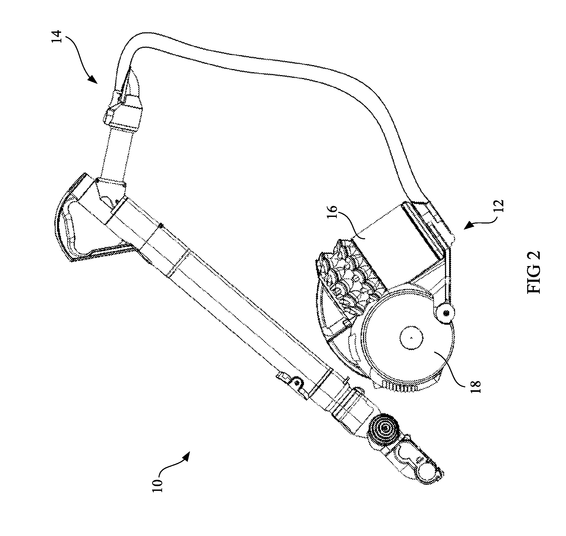
[0021]FIG. 2 illustrates an external view of a cleaning appliance in the form of a vacuum cleaner 10. The vacuum cleaner 10 is of the cylinder or canister type which typically has a body 12 which is pulled behind a hose and wand assembly 14 during use. Although FIG. 2 shows a cylinder type vacuum cleaner, the presently claimed invention can be used within any style of vacuum cleaner that comprises a cyclonic separator, other examples of which may be upright or handheld vacuum cleaners.

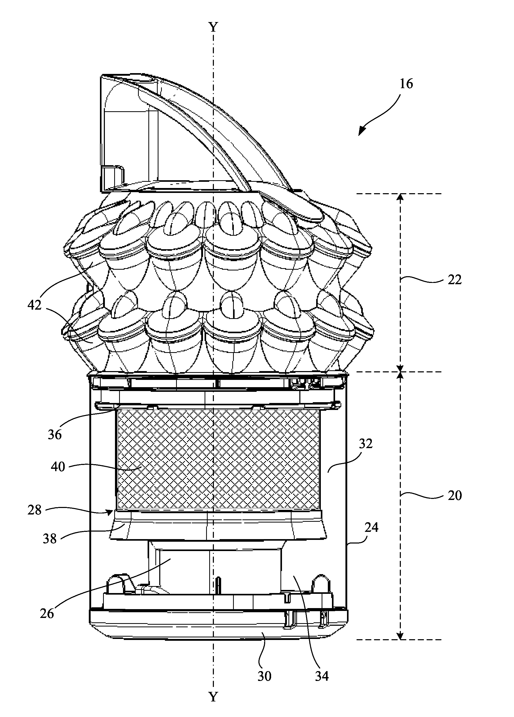
[0022]The body 12 comprises a cyclonic separator 16 for separating dirt and dust from an airflow, and a floor engaging rolling assembly 18. The cyclonic separator 16 is received within the floor engaging rolling assembly 18 such that it is at least partially nested or docked within the rolling assembly 18. Dirty air enters the body 12 from the hose and wand assembly 14 via an inlet duct, and into the cyclonic separator 16. The cyclonic separator 16 is removable from the rolling assembly 18 such that an...


PUM

PropertyMeasurementUnit
flexibleaaaaaaaaaa
tensionaaaaaaaaaa
circumferenceaaaaaaaaaa

Abstract

A cyclonic separator having an outer wall and an inner wall, and a shroud disposed between the outer wall and the inner wall, the inner wall having one or more outwardly projecting members, the shroud having upper and lower portions, and a mesh secured between the upper and lower portions, the lower portion having a flange that extends radially inward towards the inner wall, wherein the flange has one or more flexible portions, and the outwardly projecting members abut the flexible portions so as to bias the lower portion away from the upper portion to thus tension the mesh.

Description

REFERENCE TO RELATED APPLICATION This application claims priority of United Kingdom Application No. 1318596.2 filed Oct. 21, 2013, the entire contents of which are incorporated herein by reference.FIELD OF THE INVENTION[0001]The present invention relates to a cyclonic separator having a shroud.BACKGROUND OF THE INVENTION[0002]Vacuum cleaners having cyclonic separators are now well known. The cyclonic separators typically comprise a cyclone chamber defined between an outer wall and a shroud. In general, an airflow in which dirt and dust is entrained enters the cyclone chamber via an inlet which causes the airflow to follow a spiral or helical path so that the dirt and dust is separated from the airflow. Relatively clean air then passes out of the cyclone chamber through the shroud and typically will then proceed to one or more subsequent cyclonic separators. The shroud can comprise a rigid wall provided with a large number of through-holes through which the air can travel. However, a...

Claims


Application Information

Patent Timeline
Patent Type & Authority Applications(United States)
IPC IPC(8): A47L9/16B01D45/16
CPCB01D45/16A47L9/16A47L9/1666B04C5/10B04C5/103B04C5/185A47L9/1608
Inventor THOMPSON, DANIEL JOHNROBERTSON, JAMES STUARTRANDLES, SOPHIE KATHRYN
Owner DYSON TECH LTD
Why Eureka
Try Eureka