Vehicular air conditioner
a technology for air conditioners and vehicles, applied in vehicle components, vehicle heating/cooling devices, transportation and packaging, etc., can solve the problems of difficult to completely close the gap between, window may be fogged, etc., and achieve the effect of reducing pressure loss, reducing pressure from inside air passage toward outside air passage, and reducing pressure loss
- Summary
- Abstract
- Description
- Claims
- Application Information
AI Technical Summary
Benefits of technology
Problems solved by technology
Method used
Image
Examples
first embodiment
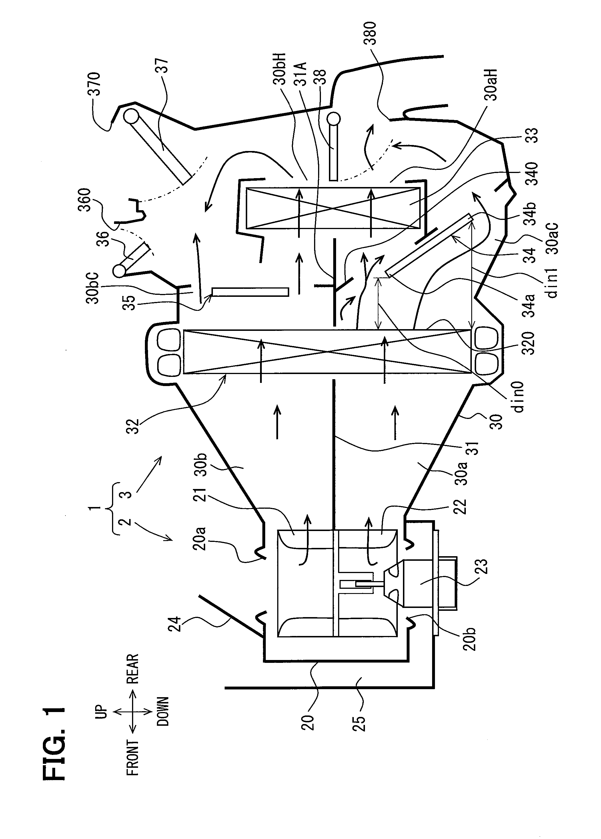
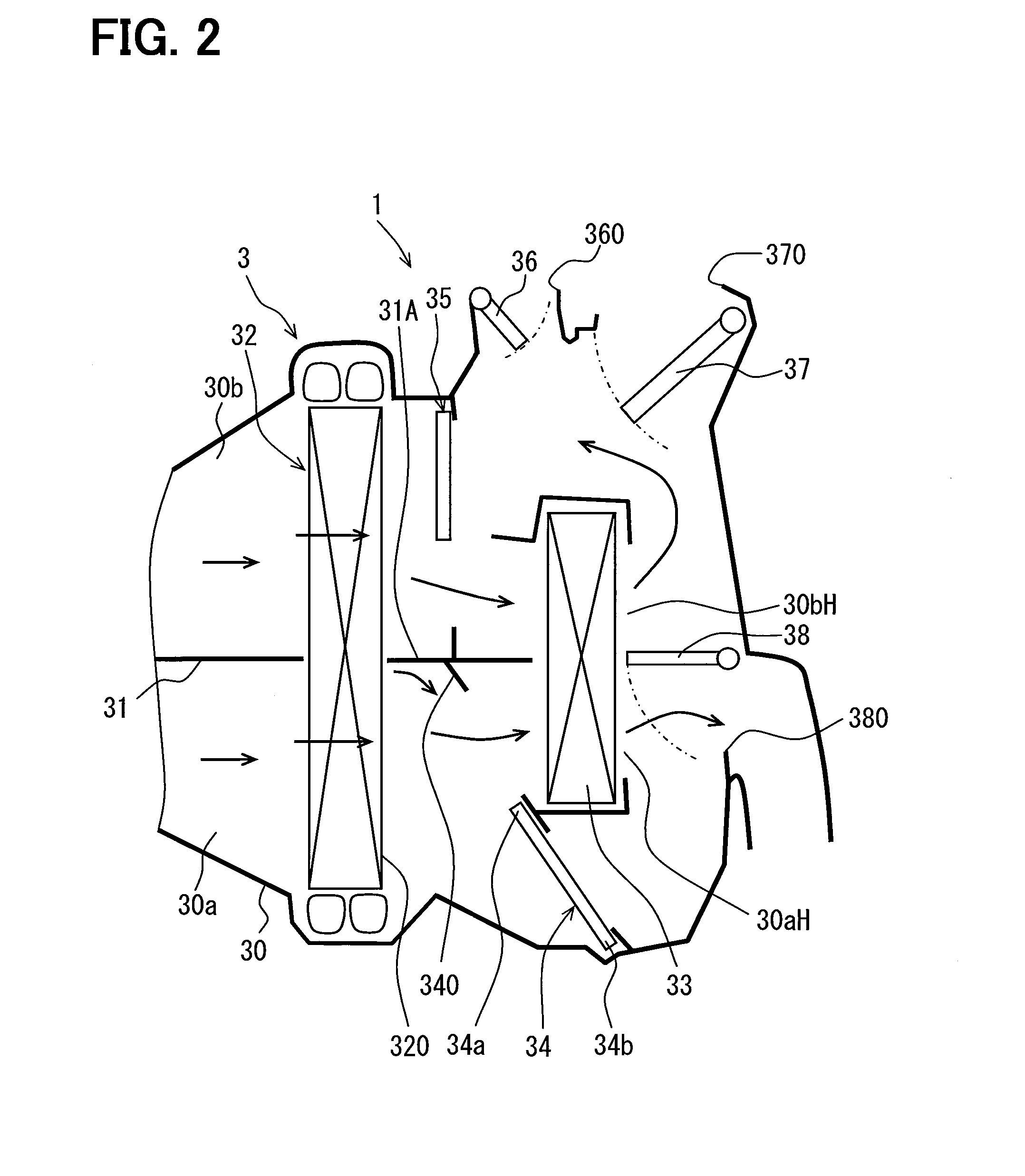
[0022]A vehicular air conditioner 1 of a first embodiment of the present disclosure will be described according to FIGS. 1 to 3. FIG. 1 is a schematic diagram showing an inner structure of the vehicular air conditioner 1 according to the first embodiment. In FIG. 1, a state where respective air mix doors 34 and 35 are provided is shown. FIG. 2 is a schematic diagram showing positions of the air mix doors 34 and 35 in a max hot operation of the vehicular air conditioner 1, in which a heating capacity of the vehicular air conditioner 1 is largest. FIG. 3 is a schematic diagram showing positions of the air mix doors 34 and 35 in a max cool operation of the vehicular air conditioner 1, in which a cooling capacity of the vehicular air conditioner 1 is largest.
[0023]The vehicular air conditioner 1 includes a blower unit 2 and an air-conditioning unit 3 that regulates a temperature of air blown from the blower unit 2. Each of the blower unit 2 and the air-conditioning unit 3 includes a res...
second embodiment
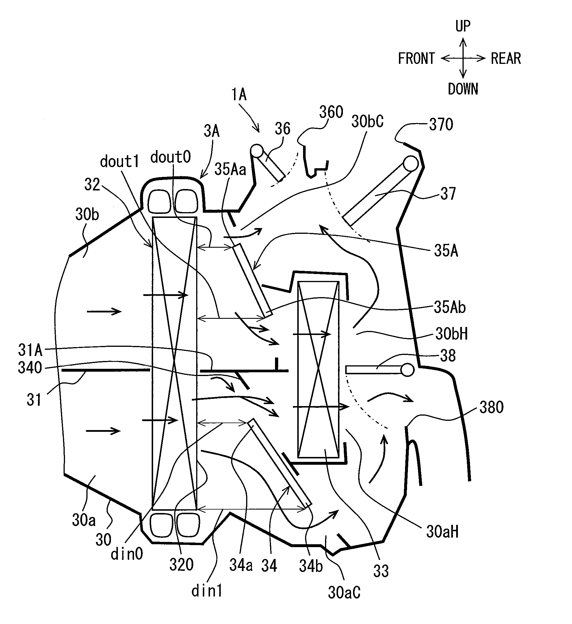
[0058]In a second embodiment, the configuration of the vehicular air conditioner of the first embodiment is changed. FIG. 4 is a schematic diagram showing an inner structure of a vehicular air conditioner 1A according to the second embodiment. Hereinafter, a configuration to which no explanation is provided is similar to that of the first embodiment, and a configuration different from the first embodiment will be explained.
[0059]In an air-conditioning unit 3A of the vehicular air conditioner 1A, a configuration of an air mix door 35A disposed in the outside-air passage is different from the first embodiment.
[0060]The air mix door 35A is a sliding door that is displaced to move parallel. The air mix door 35A includes one door end portion 35Aa and the other door end portion 35Ab that is nearer to a partitioning portion 31A than the one door end portion 35Aa. As shown in FIG. 4, a distance dout0 between an air outlet surface 320 of an evaporator 32, from which air passing through the e...
third embodiment
[0067]In a third embodiment, the configuration of the vehicular air conditioner of the first embodiment is changed. FIG. 5 is a schematic diagram showing an inner structure of a vehicular air conditioner 1B according to the third embodiment. Hereinafter, a configuration to which no explanation is provided is similar to that of the first embodiment, and a configuration different from the first embodiment will be explained.
[0068]In an air-conditioning unit 3B of the vehicular air conditioner 1B, a configuration of a heater core 33A is different from the first embodiment.
[0069]The heater core 33A includes one end portion 33Aa (first end portion) located in an outside-air passage, and the other end portion 33Ab (second end portion) located in the inside-air passage. A distance between an air outlet surface 320 of an evaporator 32 and the one end portion 33Aa is shorter than a distance between the air outlet surface 320 and the other end portion 33Ab. That is, the heater core 33A is tilt...
PUM
 Abstract
Description
Claims
Application Information
 - R&D
- Intellectual Property
- Life Sciences
- Materials
- Tech Scout
- Unparalleled Data Quality
- Higher Quality Content
- 60% Fewer Hallucinations
Browse by: Latest US Patents, China's latest patents, Technical Efficacy Thesaurus, Application Domain, Technology Topic, Popular Technical Reports.
© 2025 PatSnap. All rights reserved.Legal|Privacy policy|Modern Slavery Act Transparency Statement|Sitemap|About US| Contact US: help@patsnap.com


