Eddy current separation apparatus, separation module, separation method and method for adjusting an eddy current separation apparatus

a technology of eddy current separation and eddy current, which is applied in the direction of magnetic separation, solid separation, chemistry apparatus and processes, etc., can solve the problems of inability to obtain the accurate separation of the respective particle fractions from the bottom ash waste stream based on visual detection by means of cameras, and the investment to be made for providing the improved eddy current separation apparatus is relatively low

Inactive Publication Date: 2015-04-23
ADR TECH
View PDF17 Cites 19 Cited by
  • Summary
  • Abstract
  • Description
  • Claims
  • Application Information

AI Technical Summary

Benefits of technology

[0029]To protect the sensor device from fouling, the sensor device may be at least partly surrounded by a cover. According to a further aspect of the invention, the cover may comprise at least one sheet shaped element, wherein the sheet shaped element is provided at an angle with respect to a displacement direction of the metal particle fraction.
[0030]The invention further relates to a separating module for use with an eddy current separation apparatus, such as a known eddy current separation apparatus as described before. According to the invention, the separating module at least comprises the above described splitter element, the sensor device and the control unit. The invention also relates to a method for modifying an eddy current separation apparatus into an eddy current separation apparatus according to the invention. The meth

Problems solved by technology

Therefore, accurate separation of the respective particle fractions from the bottom ash waste stream based on visual detection by means of a camera, such as a black and white camera, colour camera, infrared camera, and the like cameras, can not be o

Method used


Image

  • Eddy current separation apparatus, separation module, separation method and method for adjusting an eddy current separation apparatus
  • Eddy current separation apparatus, separation module, separation method and method for adjusting an eddy current separation apparatus
  • Eddy current separation apparatus, separation module, separation method and method for adjusting an eddy current separation apparatus

Examples


Embodiment Construction

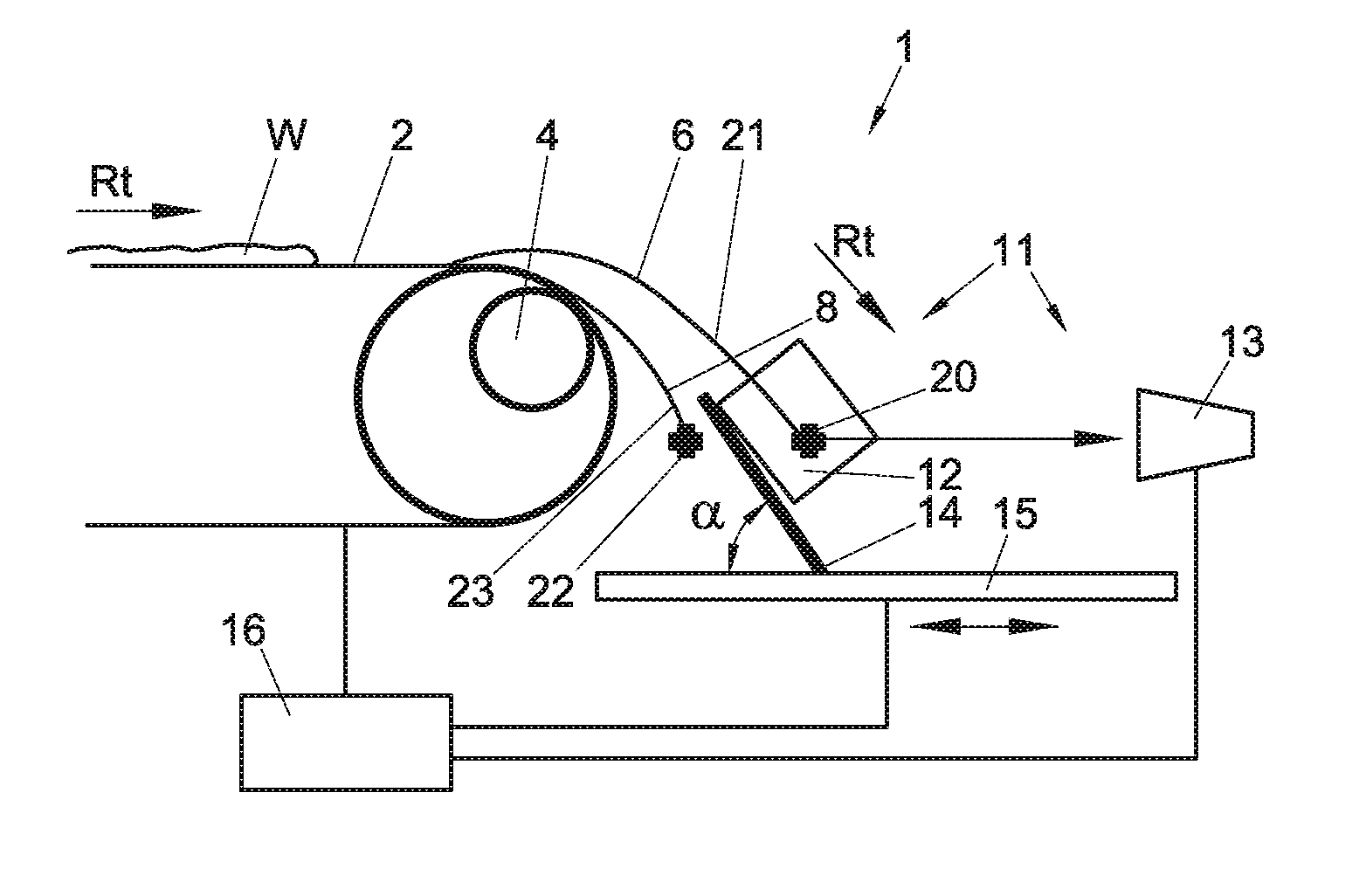
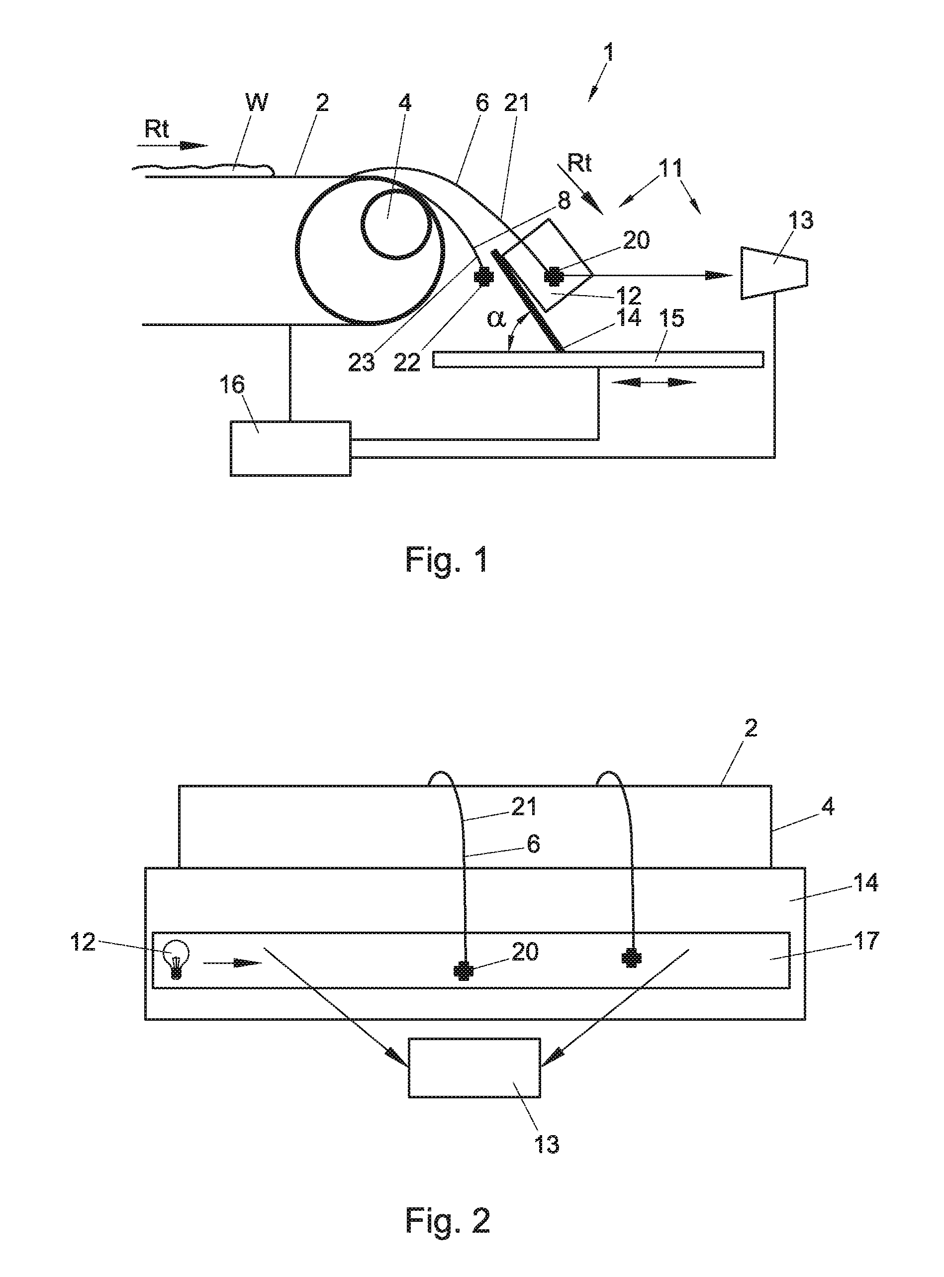
[0045]In FIGS. 1 and 2, a first example of the eddy current separation apparatus 1 according to the invention is shown. The eddy current separation apparatus 1 is adapted for separating non-ferrous metal particles 20, such as aluminium, copper, zinc and brass particles, from a waste stream W. Therefore, the eddy current separation apparatus 1 comprises a conveyor 2 for supplying a particle stream of waste material W to a separator drum 4 in a transporting direction Rt. The separator drum 4 comprises a rotatable permanent magnetic drum and is adapted to induce electric currents, i.e. eddy currents, within the volume of each particle 20, 22 flowing in the proximity of the drum 4. The influence of the magnetic field on the induced currents results in a Lorenz force which ejects the particles 20 out of the magnetic field of the drum 4 resulting in a first non-ferrous particle fraction 21 travelling along a first trajectory 6. The remainder of the particle stream, thus the part that is n...


PUM


Abstract

Eddy current separation apparatus (1) for separating particles (20) from a particle stream (w), wherein the apparatus (1) comprises a separator drum (4) adapted to create a first particle fraction (21) and a second particle fraction (23), a feeding device (2) upstream of the separator drum (4) for supplying particles (20) to said separator drum (4), and a splitter element (14) provided downstream of the separator drum (4) for splitting the respective fractions (21,23), wherein the apparatus (1) further comprises a sensor device (11,111,211) arranged for detecting particles (20), at least a number and/or material properties thereof, from at least part of one of the particle fractions (21), wherein the separation apparatus (1) is configured to adjust, in use, a position and/or orientation of the splitter element (14) with respect to the separator drum (4) and/or a transporting velocity of the feeding device (2) in dependence of a signal from the sensor device (11,111,211) based on the number and/or material properties of the detected particles (20).

Description

FIELD AND BACKGROUND OF THE INVENTION[0001]The present invention relates to eddy current separation technology. More in particular, the present invention relates to an eddy current separation apparatus for separating particles from a particle stream, wherein the separation apparatus comprises a separator drum adapted to create out of the particle stream at least a first particle fraction moving from the drum along a first trajectory and a second particle fraction moving from the drum along a second trajectory, a feeding device upstream of the separator drum for supplying particles to said separator drum, and a splitter element provided downstream of the separator drum for splitting the first particle fraction from the second particle fraction.[0002]Eddy current separation technology is commonly known for sorting and separating metal particles from a stream of particles. By using an eddy current separation apparatus, recovering metals such as aluminium from household, industrial and ...

Claims


Application Information

Patent Timeline
IPC IPC(8): B03C1/30B03C1/247
CPCB03C1/247B03C1/30B03C2201/24B03C2201/20B03C1/02
Inventor REM, PETER CARLOBAKKER, MARTINUS CORNELIS MARIABERKHOUT, SIMON PETER MARIARAHMAN, MOHAMMED ABDUR
Owner ADR TECH
Why Eureka
Try Eureka