Array substrate and 3D display device

Inactive Publication Date: 2015-04-23
TCL CHINA STAR OPTOELECTRONICS TECH CO LTD
View PDF3 Cites 0 Cited by
  • Summary
  • Abstract
  • Description
  • Claims
  • Application Information

AI Technical Summary

Benefits of technology

The present invention provides an array substrate and a 3D display device that can improve display quality when showing high-brightness pictures. This is achieved by inserting grey-scale pictures with varying brightness levels using a special mode called "BLU blinking." The invention solves the issue of display quality decreasing when showing only one type of grey-level picture in conventional 3D display technologies.

Problems solved by technology

However, this technology is only able to insert the black pictures.
This technology cannot insert pictures with varied brightness according to different 3D modes.
This limits the development of 3D display technology.
For instance, when a high-brightness grey-scale picture is required, it may lead the 3D display quality become worse (e.g., low brightness) if just inserting the black pictures.

Method used


Image

  • Array substrate and 3D display device
  • Array substrate and 3D display device
  • Array substrate and 3D display device

Examples


Embodiment Construction

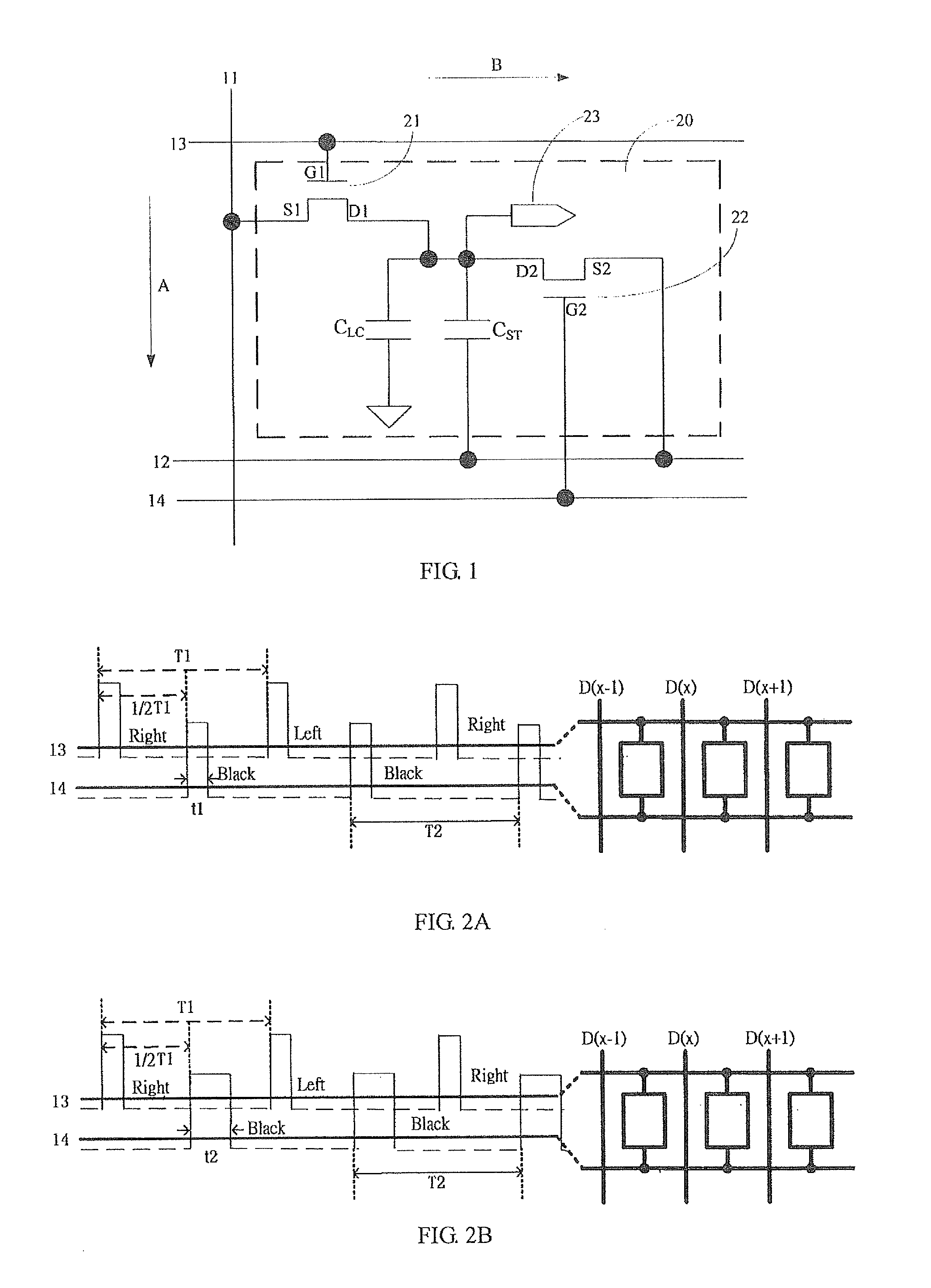
[0029]The following descriptions for the respective embodiments are specific embodiments capable of being implemented for illustrations of the present invention with referring to appended figures. In the descriptions of the present invention, spatially relative terms, such as “upper”, “lower”, “front”, “back”, “left”, “right”, “inner”, “outer”, “lateral”, and the like, may be used herein for case of description as illustrated in the figures. Therefore, it will be understood that the spatially relative terms are intended to illustrate for understanding the present invention, but not to limit the present invention. In the appending drawings, units having similar structures are labeled by the same reference numbers.

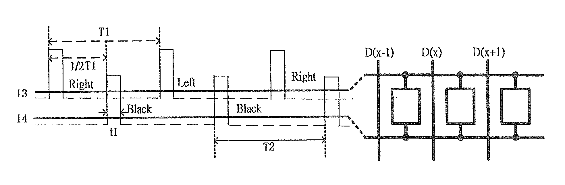
[0030]Please refer to FIG. 1, which is a schematic diagram showing an array substrate according to a preferred embodiment of the present invention. The array substrate comprises a data line 11 extended along a column direction A, and also comprises a common electrode line 12...


PUM


Abstract

In the present invention, after the corresponding thin-film transistor is turned on by a first scan line, charging is achieved through a pixel electrode. After that, the corresponding thin-film transistor is turned on by a second scan line. The common voltage starts to be applied to the pixel electrode. In such a manner, the insertion of grey-scale pictures is carried out. Moreover, the embodiments of the present invention control the duration of time of a second scan signal on the second scan line so as to pull down the voltage of the pixel electrode to different voltage levels, thereby achieving the insertion of grey-scale pictures with varied brightness.

Description

BACKGROUND OF THE INVENTION[0001]1. Field of the Invention[0002]The present invention relates to a 3D display technology, and more particularly, to an array substrate and a 3D display device.[0003]2. Description of Prior Art[0004]As 3D applications are gradually propagated and promoted, the demands on 3D technology are higher and higher.[0005]3D shutter glasses often use a technology called Black Insertion or BLU Blinking Mode, which is a backlight scan mode with insertion of black pictures. In this 3D technology, when inserting the black pictures, it is often controlled by TCON (a timing controller) or SE (a converter) of a 3D display. This technology is carried out by inserting black pictures when the left-eye and right-eye signals are switched. For example, one black picture is inserted in the end of a right-eye frame and then a left-eye frame is scanned and displayed.[0006]However, this technology is only able to insert the black pictures. That is, only one kind of brightness fo...

Claims


Application Information

Patent Timeline
IPC IPC(8): G09G3/20
CPCG09G3/2092G09G2310/06G09G2300/08G09G2310/0262G09G2320/0233G09G3/003G09G3/20G09G3/3655G09G3/3659G09G2340/0435H04N13/341H04N13/398
Inventor CHEN, CHENGHUNGJIANG, JIALI
Owner TCL CHINA STAR OPTOELECTRONICS TECH CO LTD
Why Eureka
Try Eureka