Excitation module, laser oscillator, and laser amplifier

Inactive Publication Date: 2006-05-09
MITSUBISHI ELECTRIC CORP
View PDF11 Cites 1 Cited by
  • Summary
  • Abstract
  • Description
  • Claims
  • Application Information

AI Technical Summary

Benefits of technology

[0032]As a result, the present invention offers an advantage of being able to prevent any decrease in the extinction ratio regardless of a variation in the orientation of the birefringence axes of each of the plurality of square rods, and to prevent the occurrence of a difference between a thermal lens with respect to the direction of the first axis and another thermal lens with respect to the direction of the second axis, thereby preventing the occurrence of astigmatism.
[0066]As a result, the present invention provides another advantage of being able to prevent any decrease in the efficiency of energy and any decrease in the beam quality without having to use a mechanism of compensating for astigmatism.

Problems solved by technology

Therefore, a problem encountered in the pumping module is that a mechanism of compensating for astigmatism is needed when the pumping module of FIG. 1 is used for such a laser apparatus as a laser oscillator or a laser amplifier, just as it is, and the optical system structure thus becomes complex.
Thus a problem encountered in the prior art laser oscillator is that it is difficult for heat to be ideally dissipated only in the direction of the y axis, and the direction of the temperature gradients is not parallel to the direction of the y axis and therefore there causes an inclination in the direction of the temperature gradients.
2 is applied to such a laser apparatus as a laser oscillator or a laser amplifier, a decrease in the efficiency of energy and a decrease in the beam quality can occur.
Therefore, a problem with the prior art pumping module is that a mechanism of compensating for astigmatism is needed for such a laser apparatus to which the pumping module of FIG. 2 is applied as a laser oscillator or a laser amplifier, and the optical system structure thus becomes complex.
A problem with prior art pumping modules constructed as mentioned above is that the extinction ratio of laser light passing through the square rod is decreased because it is difficult to provide ideal heat sinking such that temperature gradients are produced only in the direction of the y axis and this results in occurrence of a variation in the orientation of the birefringence axes.
Another problem with prior art pumping modules is that astigmatism occurs because a thermal lens effect is also produced in the direction of the x axis.
Another problem encountered in such a laser apparatus to which a prior art pumping module is applied as a laser oscillator or a laser amplifier is that a decrease in the efficiency of energy and a decrease in the beam quality can occur, and a mechanism of compensating for astigmatism is needed and the optical system structure thus becomes complex.

Method used


Image

  • Excitation module, laser oscillator, and laser amplifier
  • Excitation module, laser oscillator, and laser amplifier
  • Excitation module, laser oscillator, and laser amplifier

Examples


embodiment 1

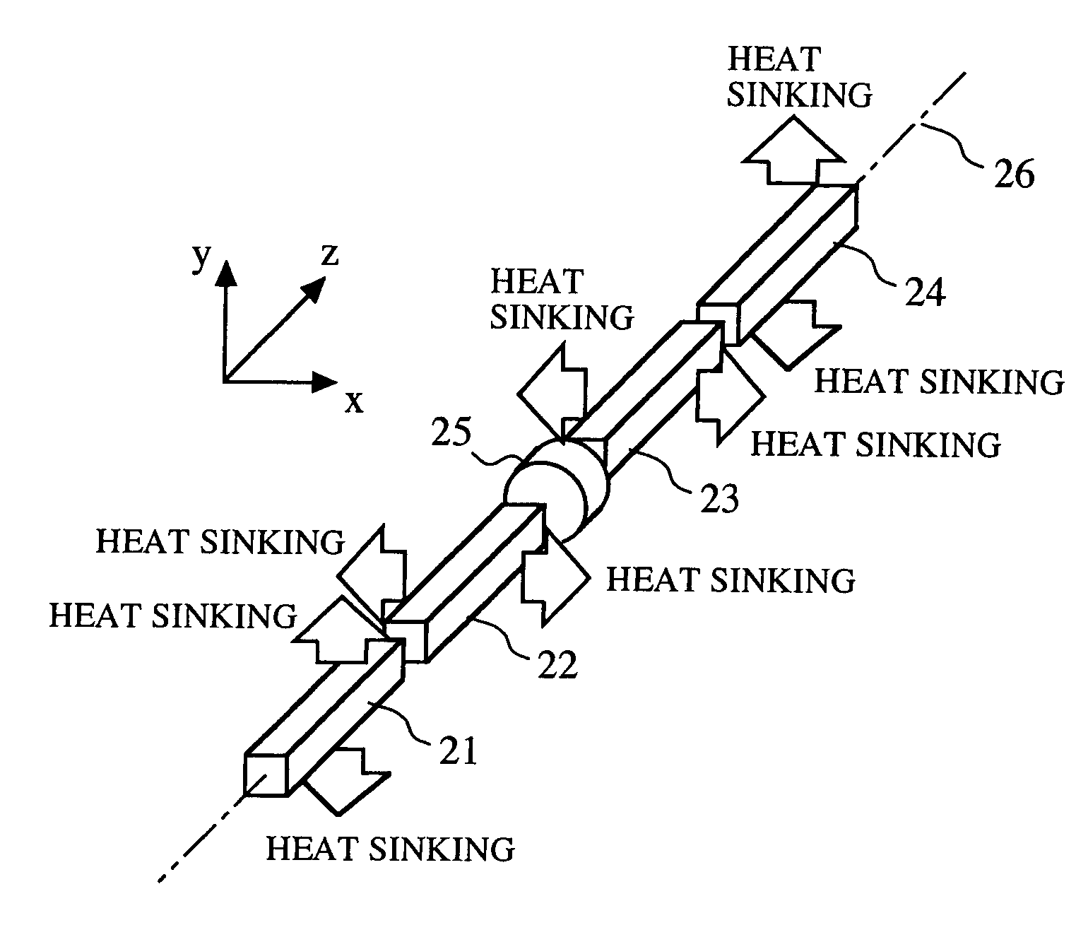
[0081]FIG. 4 is a diagram showing the structure of a pumping module according to embodiment 1 of the present invention. The pumping module is constructed of a plurality of square rods.

[0082]In FIG. 4, reference numeral 21 denotes a first square rod (first square rod group), reference numeral 22 denotes a second square rod (first square rod group), reference numeral 23 denotes a third square rod (second square rod group), reference numeral 24 denotes a fourth square rod (second square rod group), reference numeral 25 denotes a 90-degree polarization rotator, and reference numeral 26 denotes an optical axis which the first through fourth square rods 21 to 24 and the 90-degree polarization rotator 25 have in common.

[0083]As shown in FIG. 4, the first square rod 21 has a couple of heat sinking surfaces which are normal to a direction of y axis (a direction of a first axis), and the fourth square rod 24 has a couple of heat sinking surfaces which are normal to the direction of the y axis...

embodiment 2

[0130]FIG. 7 is a diagram showing the structure of a pumping module according to embodiment 2 of the present invention.

[0131]In FIG. 7, reference numeral 27 denotes a fifth square rod, reference numeral 28 denotes a sixth square rod, and reference numerals 25 and 26, which are also shown in FIG. 1, denote a 90-degree polarization rotator and an optical axis, respectively. The fifth and sixth square rods 27 and 28 and the 90-degree polarization rotator 25 have the optical axis 26 in common.

[0132]In the fifth square rod 27, heat generated in a half of thereof is dissipated in a direction of y axis and heat generated in the remaining half thereof is dissipated in a direction of x axis, and in the sixth square rod 28, heat generated in a half of thereof is dissipated in the direction of the x axis and heat generated in the remaining half thereof is dissipated in the direction of the y axis.

[0133]In other words, it can be considered that the fifth square rod 27 is equivalent to the one i...

embodiment 3

[0139]FIG. 8 is a diagram showing the structure of a pumping module according to embodiment 3 of the present invention.

[0140]In FIG. 8, reference numeral 31 denotes a seventh square rod, reference numeral 32 denotes an eighth square rod, reference numeral 33 denotes a ninth square rod, reference numeral 34 denotes a tenth square rod, reference numeral 35 denotes a first 90-degree polarization rotator, and reference numeral 36 denotes a second 90-degree polarization rotator. Reference numeral 26, which is also shown in FIG. 1, denotes an optical axis. The seventh through tenth square rods 31 to 34 and the first and second 90-degree polarization rotators 35 and 36 have the optical axis 26 in common.

[0141]Both a couple of heat sinking surfaces of the seventh square rod 31 and a couple of heat sinking surfaces of the eighth square rod 32 are normal to a direction of y axis and both a couple of heat sinking surface of the ninth square rod 33 and a couple of heat sinking surface of the te...


PUM


Abstract

A pumping module is provided with a first square rod group including a first square rod having two heat sinking surfaces normal to a direction of y axis perpendicular to an optical axis, and a second square rod having two heat sinking surfaces normal to a direction of x axis perpendicular to the optical axis and the direction of the y axis, and a second square rod group including a third square rod having two heat sinking surfaces normal to the direction of the y axis and a fourth square rod having two heat sinking surfaces normal to the direction of the x axis. A polarization rotator is disposed between the first and second square rod groups, for rotating a polarization of laser light passing therethrough by 90 degrees.

Description

[0001]This application is the national phase under 35 U.S.C. § 371 of PCT International Application No. PCT / JP01 / 05316 which has an International filing date of Jun. 21, 2001, which designated the United States of America.FIELD OF THE INVENTION[0002]The present invention relates to a pumping module that makes laser light pass through a square rod that absorbs pump light incident thereon so as to provide a gain for the laser light. It also relates to a laser oscillator that uses the pumping module and a laser amplifier that uses the pumping module.BACKGROUND OF THE INVENTION[0003]In a square rod (rectangular rod or slab) formed in the form of a square pillar, which is used as a laser medium for a solid state laser apparatus, it is easy to install a mechanism (metallic heat sink or the like) for dissipating heat generated in the square rod from a couple of lateral surfaces facing each other which serve as heat sinking surfaces and it is therefore easy to dissipate the heat from the sq...

Claims


Application Information

Patent Timeline
IPC IPC(8): H01S3/091H01S3/042H01S3/06H01S3/08H01S3/081H01S3/0941H01S3/23
CPCH01S3/042H01S3/0606H01S3/07H01S3/0941H01S3/23H01S3/08072H01S3/2316H01S3/0813H01S3/08095
Inventor YANAGISAWA, TAKAYUKIHIRANO, YOSHIHITO
Owner MITSUBISHI ELECTRIC CORP
Why Eureka
Try Eureka