Image processing system, image processing method executed by computer and non-transitory storage medium storing image processing program executed by computer

Active Publication Date: 2018-09-13
TOYOTA JIDOSHA KK
View PDF3 Cites 0 Cited by
  • Summary
  • Abstract
  • Description
  • Claims
  • Application Information

AI Technical Summary

Benefits of technology

The patent text describes an image processing system, method, and non-transitory storage medium that allow for changing the quality of images captured by a camera in a vehicle. The system can consider factors such as vehicle position and the needs of the image output requestor to adjust image quality. Ultimately, the technology allows for better quality control and management in vehicle cameras.

Problems solved by technology

Increase in the resolution of an image picked up by the camera facilitates analyses of traveling environment and the like, but can cause a problem about privacy.
However, currently, it is not possible to change the resolution of the image picked up by the camera provided in the vehicle, depending on vehicle positions or users (users who analyze the image).

Method used


Image

  • Image processing system, image processing method executed by computer and non-transitory storage medium storing image processing program executed by computer
  • Image processing system, image processing method executed by computer and non-transitory storage medium storing image processing program executed by computer
  • Image processing system, image processing method executed by computer and non-transitory storage medium storing image processing program executed by computer

Examples


embodiment 1

[0034]In an embodiment 1, an image processing system includes a processing device 7.

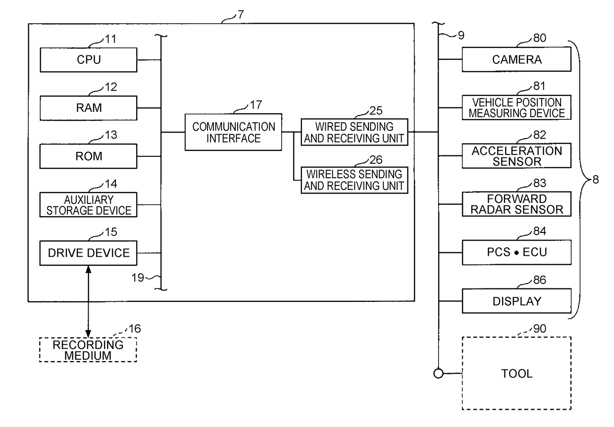
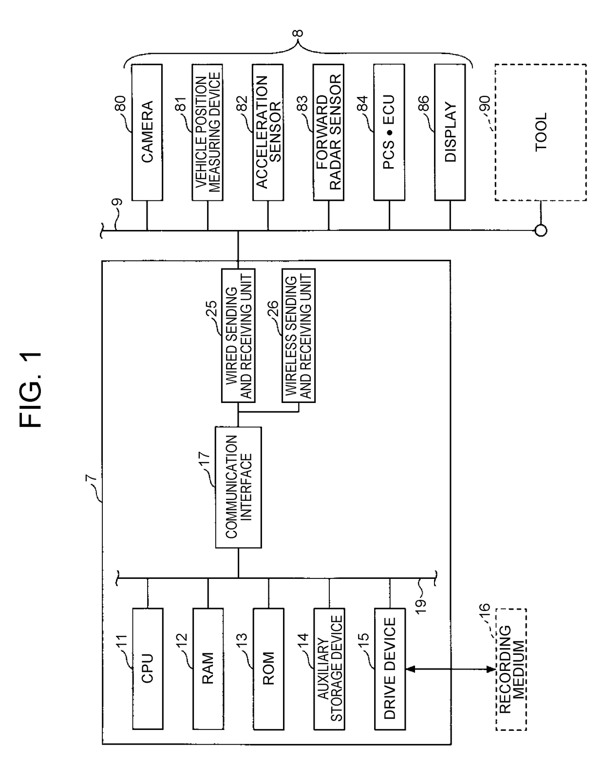
[0035]FIG. 1 is a diagram showing an exemplary hardware configuration of the processing device 7 in the embodiment 1. In FIG. 1, an in-vehicle electronic device group 8 is schematically illustrated in association with the hardware configuration of the processing device 7. The processing device 7 is connected to the in-vehicle electronic device group 8, through a vehicle network 9 such as Controller Area Network (CAN), Local Interconnect Network (LIN) and Ethernet®, for example.

[0036]The processing device 7 includes a Central Processing Unit (CPU) 11, a Random Access Memory (RAM) 12, a Read Only Memory (ROM) 13, an auxiliary storage device 14, a drive device 15, and a communication interface 17, which are connected through a bus 19. Further, the processing device 7 includes a wired sending and receiving unit 25 and a wireless sending and receiving unit 26, which are connected to the communication inte...

embodiment 2

[0091]In the embodiment 2, an image processing system includes a processing device 7A. The embodiment 2 is different from the above-described embodiment 1 in timing of the resolution changing process. In the following, characteristic constituents in the embodiment 2 will be mainly described. In the embodiment 2, identical reference characters are assigned to constituent elements that may be the same as those in the above-described embodiment 1, and descriptions thereof will be omitted, in some cases.

[0092]FIG. 10 is a diagram showing an exemplary functional block of the processing device 7A in the embodiment 2.

[0093]The processing device 7A in the embodiment 2 has the same hardware configuration as the processing device 7 in the above-described embodiment 1, but is different in that the image storing processing unit 724, the resolution changing unit 726 and the image output processing unit 728 are replaced with an image storing processing unit 724A, a resolution changing unit 726A (...

embodiment 3

[0108]In the embodiment 3, an image processing system includes a processing device 7B and a server 3. That is, the image processing system is provided so as to be divided between the vehicle and the server 3. In the following, characteristic constituents in the embodiment 3 will be mainly described. In the embodiment 3, identical reference characters are assigned to constituent elements that may be the same as those in the above-described embodiment 1, and descriptions thereof will be omitted, in some cases.

[0109]FIG. 12 is a schematic configuration diagram showing an exemplary image processing system 1. The image processing system 1 includes the processing device 7B and the server 3. The processing device 7B and the server 3 can communicate with each other. For example, the processing device 7B includes the wireless sending and receiving unit 26 (see FIG. 1), and thereby, can communicate with the server 3.

[0110]FIG. 13 is a diagram showing exemplary functional blocks of the process...


PUM


Abstract

An image processing system includes: an image acquiring unit that acquires an image picked up by a camera, the camera being provided in a vehicle; and a quality changing unit that performs a quality changing process of decreasing a quality of the image to equal to or lower than a predetermined standard, based on at least one of a vehicle position at a time when the image is picked up, a vehicle position at a time when the image is output to an external device or a display device, and requestor information that indicates a requestor of an output request of the image.

Description

INCORPORATION BY REFERENCE[0001]The disclosure of Japanese Patent Application No. 2017-045351 filed on Mar. 9, 2017 including the specification, drawings and abstract is incorporated herein by reference in its entirety.BACKGROUND1. Technical Field[0002]The disclosure relates to an image processing system, an image processing method executed by a computer and a storage medium holding an image processing program executed by a computer.2. Description of Related Art[0003]There is known an authentication system that performs a determination of whether a managed object such as a construction machine can be used, using positional information of the managed object (see Japanese Patent Application Publication No. 2008-191825, for example).SUMMARY[0004]In recent years, many vehicles are equipped with cameras such as a so-called drive recorder. Increase in the resolution of an image picked up by the camera facilitates analyses of traveling environment and the like, but can cause a problem abou...

Claims


Application Information

Patent Timeline
IPC IPC(8): H04N5/262B60K31/00
CPCH04N5/2628B60K31/0008B60K2350/1084B60K2031/0016B60K2031/0025B60K2031/0033G06T3/4023B60R1/00H04N5/76H04N5/91B60R2300/30H04N23/60G06T3/40B60K35/28B60K2360/179
Inventor NAKADA, HIROSHI
Owner TOYOTA JIDOSHA KK
Why Eureka
Try Eureka