
Ultrasound diagnostic apparatus

Active Publication Date: 2018-05-03
KONICA MINOLTA INC
View PDF0 Cites 0 Cited by
  • Summary
  • Abstract
  • Description
  • Claims
  • Application Information

AI Technical Summary

Benefits of technology

The technical effect of the present invention is to provide an ultrasound diagnostic apparatus that can maintain good power supply efficiency while maintaining the quality of the ultrasound image.

Problems solved by technology

Unfortunately, such an ultrasound diagnostic apparatus has the drawback that the coils of the voltage conversion circuits generate a magnetic field which leaks out of the coils, and the induced electromotive force of the leakage magnetic field generates a noise in the received ultrasound signals, decreasing the quality of an ultrasound image.
Unfortunately, the traditional technique described above cannot necessarily operate the voltage conversion circuits at optimal frequencies, resulting in low power conversion efficiency in the power supply.
Another problem is the operation of multiple voltage conversion circuits at different frequencies, complicating the control of the power supply.

Method used


Image

  • Ultrasound diagnostic apparatus
  • Ultrasound diagnostic apparatus
  • Ultrasound diagnostic apparatus

Examples


Embodiment Construction

[0021]The embodiments of an ultrasound diagnostic apparatus according to the present invention will now be described in reference to the accompanying drawings.

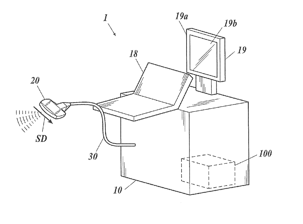
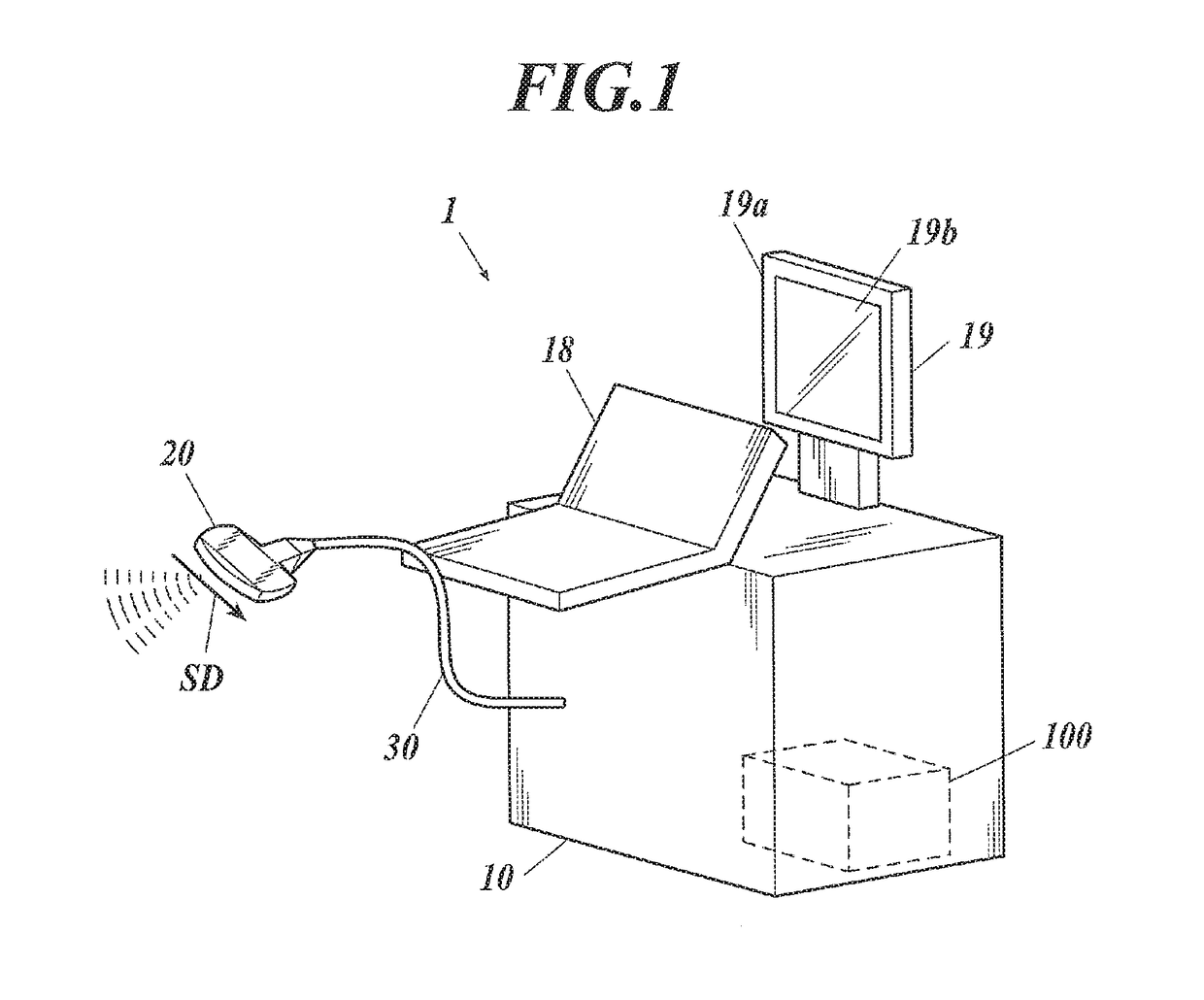
[0022]FIG. 1 is a schematic view of an ultrasound diagnostic apparatus 1 according to an embodiment of the present invention.

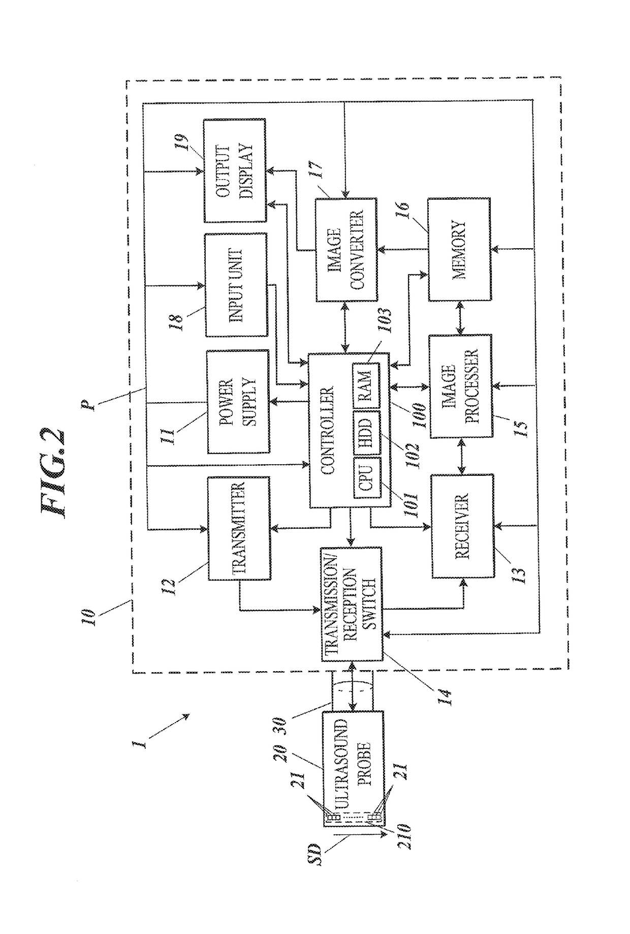
[0023]FIG. 2 is a block diagram illustrating major functional components of the ultrasound diagnostic apparatus 1.

[0024]As illustrated in FIG. 1, the ultrasound diagnostic apparatus 1 includes an ultrasound diagnostic apparatus main body 10 and an ultrasound probe 20 connected with the ultrasound diagnostic apparatus main body 10 via a cable 30a. The ultrasound diagnostic apparatus main body 10 includes, for example, a controller 100, an input unit 18, an output display 19 having a display 19a and a touch panel 19b. The controller 100 outputs driving signals to the ultrasound probe 20, causes it to output ultrasound in response to the input operation by an operator through input devices, such as a keyboa...


PUM


Abstract

An ultrasound diagnostic apparatus includes an ultrasound probe and a display. The apparatus includes a power supply including at least one voltage converting circuit converting input voltage to a predetermined power voltage for output. The voltage converting circuit includes a coil and a switching element performing a switching operation for switching routes of current flowing in the coil in response to a predetermined switching control signal, and the voltage converting circuit outputs the power voltage through the repeated switching operations under supply of the input voltage. The power supply is provided with a plurality of coils, and the coils are disposed such that a leakage magnetic field in a vicinity of an aperture of at least one of the coils is partially negated by a leakage magnetic field from one or more of the other coils.

Description

CROSS REFERENCES TO RELATED APPLICATIONS[0001]The present invention claims priority under 35 U.S.C. § 119 to Japanese Patent Application 2016-214791, filed Nov. 2, 2016, the entire contents of which being incorporated herein by reference.BACKGROUNDTechnological Field[0002]The present invention relates to an ultrasound diagnostic apparatus.Description of the Related Art[0003]A traditional ultrasound diagnostic apparatus emits ultrasound from an ultrasound probe toward a subject of interest, receives the reflected waves from the subject, processes the received signals, generates an ultrasound image corresponding to the internal structure of the subject, and displays the ultrasound image on a display. The ultrasound image provides diagnostic information of the internal structure. Such an ultrasound diagnostic apparatus is also used as a noninvasive diagnostic device for medical care for humans.[0004]This type of ultrasound diagnostic apparatus includes a power supply having multiple vo...

Claims


Application Information

Patent Timeline
IPC IPC(8): A61B8/00A61B8/14
CPCA61B8/56A61B8/461A61B8/4444A61B8/14A61B8/4494A61B8/5207A61B8/5269
Inventor MURAMATSU, YUKINAKAMURA, YASUHIROKIMURA, YOSUKE
Owner KONICA MINOLTA INC
Learn More