Manufacturing method for tank

Active Publication Date: 2020-09-10
TOYOTA JIDOSHA KK
View PDF0 Cites 0 Cited by
  • Summary
  • Abstract
  • Description
  • Claims
  • Application Information

AI Technical Summary

Benefits of technology

The present patent is about a manufacturing method for a tank that can prevent the formation of voids and increase in the volume fraction of fiber in the fiber reinforced resin layer. The method involves heating the uncured fiber reinforced resin layer using low-frequency induction heating to soften it and release air and gas from inside. Afterward, a second heating step is performed using high-frequency induction heating to harden the outer layer of the fiber reinforced resin layer faster than the inner layer, preventing the resin from seeping from the outer layer. By maintaining the innermost and outermost layers of the fiber reinforced resin layer at a low viscosity state for a predetermined time, the method ensures effective release of air and gas and prevents voids from forming inside the resin layer. Overall, this method provides a way to produce tanks with improved quality and strength.

Problems solved by technology

Further, in a case where air or gas in the fiber reinforced resin layer is hard to be released outside at the time when the fiber reinforced resin layer is hardened by heating, voids are formed inside the fiber reinforced resin layer, thereby causing a poor appearance and a decrease in quality.
Note that, when the uncured fiber reinforced resin layer is heated only by the high-frequency induction heating without the low-frequency induction heating after the step of preparing the tank in which the uncured fiber reinforced resin layer is formed on the liner, an outermost layer of the fiber reinforced resin layer hardens, so that the air and the gas in the inner layer are hard to be released outside, thereby resulting in that voids are formed inside the fiber reinforced resin layer.

Method used


Image

  • Manufacturing method for tank
  • Manufacturing method for tank
  • Manufacturing method for tank

Examples


Embodiment Construction

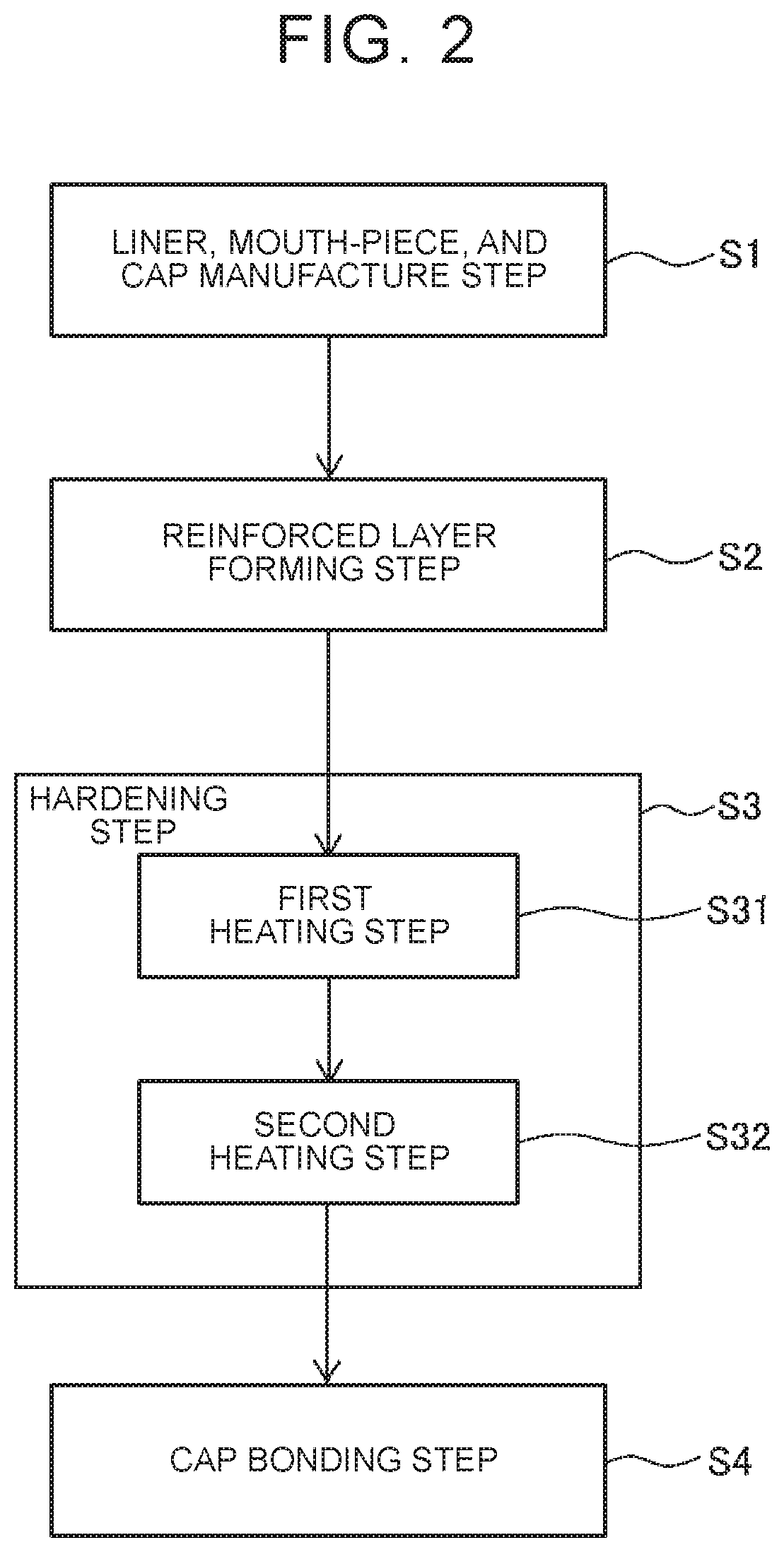
[0023]With reference to drawings, the following describes a manufacturing method for a high-pressure tank 10 according to an embodiment of the present disclosure. Note that the high-pressure tank 10 is one example of a “tank” in the present disclosure.

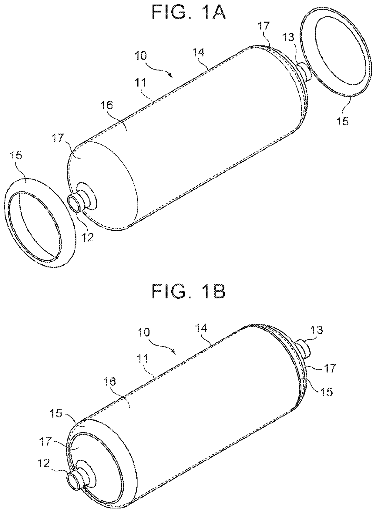
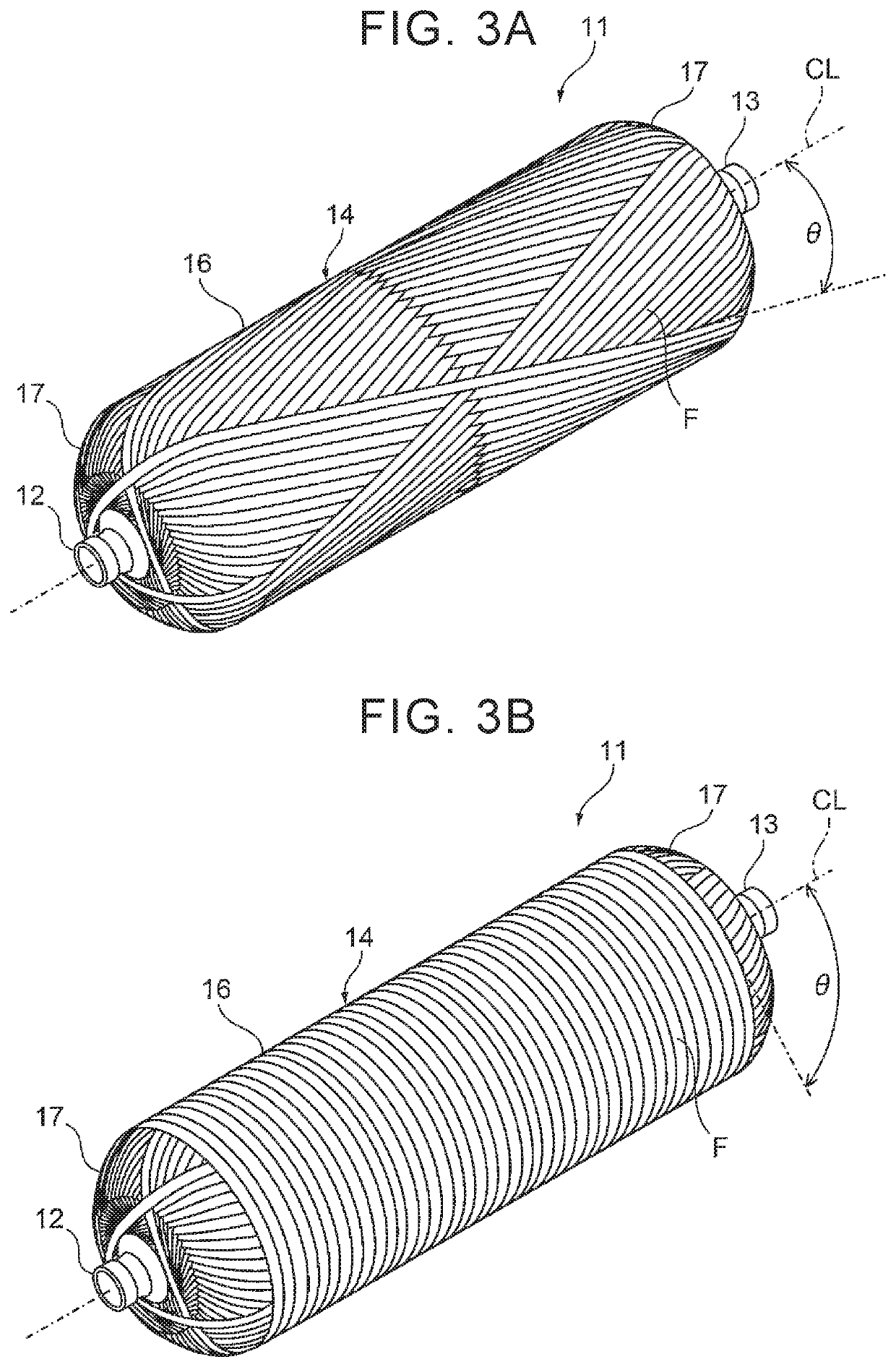
[0024]First described is the configuration of the high-pressure tank 10. As illustrated in FIGS. 1A, 1B, the high-pressure tank 10 is constituted by a liner 11, mouth pieces 12, 13, a reinforced layer (fiber reinforced resin layer) 14 formed on an outer peripheral surface of the liner 11, and a pair of caps 15. The high-pressure tank 10 has such a property that gas hardly passes through the high-pressure tank 10, i.e., a so-called gas barrier property, and is configured such that relatively high-pressure gas such as hydrogen is to be filled inside the high-pressure tank 10.

[0025]The liner 11 is constituted by a tubular hollow container and made of resin having a gas barrier property. A resin material of the liner 11 can be, for example...


PUM

PropertyMeasurementUnit
Temperatureaaaaaaaaaa
Pressureaaaaaaaaaa
Electrical conductivityaaaaaaaaaa

Abstract

A manufacturing method for a high-pressure tank is a manufacturing method for a high-pressure tank including a reinforced layer formed such that an electrically conductive fiber bundle impregnated with thermosetting resin is wound around a liner. The manufacturing method includes: a step of preparing the tank in which the uncured reinforced layer is formed on the liner; a first heating step of heating the uncured reinforced layer by low-frequency induction heating so the thermosetting resin is softened; and a second heating step of, after the first heating step, heating the softened reinforced layer by high-frequency induction heating so that the softened reinforced layer is hardened.

Description

INCORPORATION BY REFERENCE[0001]The disclosure of Japanese Patent Application No. 2019-041132 filed on Mar. 7, 2019 including the specification, drawings and abstract is incorporated herein by reference in its entirety.BACKGROUND1. Technical Field[0002]The present disclosure relates to a manufacturing method for a tank including a fiber reinforced resin layer formed such that a fiber bundle is wound around a liner.2. Description of Related Art[0003]In the related art, there has been known a tank including a tank body and a mouth piece portion attached to an open end portion of the tank body in its longitudinal direction, as a high-pressure tank (a high-pressure gas storage container) used for storage and supply of hydrogen or the like. The tank body has a two-layer structure constituted by, for example, a liner in which hydrogen gas is held airtightly, and a fiber reinforced resin layer reinforced by winding a fiber bundle made of carbon fiber reinforced plastics (CFRP) around an ou...

Claims


Application Information

Patent Timeline
IPC IPC(8): B29C63/00
CPCB29C63/0069B29K2995/0005B29K2101/10B29L2031/712B29C63/0021F17C1/16F17C1/06B29C70/342B29C70/54B29C65/48F17C2203/0663F17C2203/012F17C2209/2154F17C2209/227F17C2209/232F17C2221/012B29L2031/7156B29C63/10B29C53/005B29C53/602B29C53/66B29C53/845B29C53/822Y02E60/32
Inventor HATTA, KEN
Owner TOYOTA JIDOSHA KK
Why Eureka
Try Eureka