Pulling type drive shaft-fitting jig assembly

Inactive Publication Date: 2008-07-17
HYUNDAI MOBIS CO LTD
View PDF5 Cites 3 Cited by
  • Summary
  • Abstract
  • Description
  • Claims
  • Application Information

AI Technical Summary

Benefits of technology

[0009]Embodiments of the present invention provides a pulling type drive shaft-fitting jig assembly in which a drive shaft located on the axis of an axle hub is horizontally pulled in the axial direction of the axle hub when the drive shaft is fitted into the hub, a connection hole of the axle hub. Therefore, the peripheral components of the axle hub are not damaged by the fitted drive shaft nor decreased in quality.
[0010]Further, according to embodiments of the invention, a jig assembly that fits the drive shaft into the axle hub while pulling the end horizontally in the axial direction of the axle hub is used. Accordingly, it is possible to fit the drive shaft in the axle hub without specific equipment for supporting and pressing the drive shaft, maintaining the position of the axle hub. Therefore, it is possible to manufacture the entire equipment for the jig assembly in a small size and save manufacturing and managing cost.
[0012]Further, according to embodiments of the invention, fitting of the drive shaft in the axle hub is achieved by a small jig assembly using hydraulic or pneumatic pressure. Accordingly, the fitting can be made in an assembly line of the axle hub and the drive shaft, not a specific work place. Therefore, it is possible to prevent inefficiency due to preparation and maintenance of a specific work place.
[0020]The connection groove of the pulling socket has an open slot that is open to a side to easily fit the insert end of the connecting end and an insertion that is in close contact with the sides to axially restrict the fitted insert end.

Problems solved by technology

However, because the equipment for forcible fitting require devices that locate the axle hub, and support and press down the drive shaft, generally a large work place and at least three operators are needed for assembly and supply of components with high equipment cost.
Further, since the end of the drive shaft is fitted into the axle hub that is in place by high pressure in the equipment, the constant velocity joint of the axle hub may be damaged, or if severed, broken in fitting the drive shaft.
Accordingly, it is difficult to maintain the quality.
Further, because the vertically pressed position of the drive shaft should be accurately aligned with the axle hub in fitting, compatibility between the axle hub and peripheral components, such as the constant velocity joint, is bad in fitting the drive shaft, and if the assembly compatibility is severe, cost for changing the design and improving the quality is increased.

Method used


Image

  • Pulling type drive shaft-fitting jig assembly
  • Pulling type drive shaft-fitting jig assembly
  • Pulling type drive shaft-fitting jig assembly

Examples


case 13

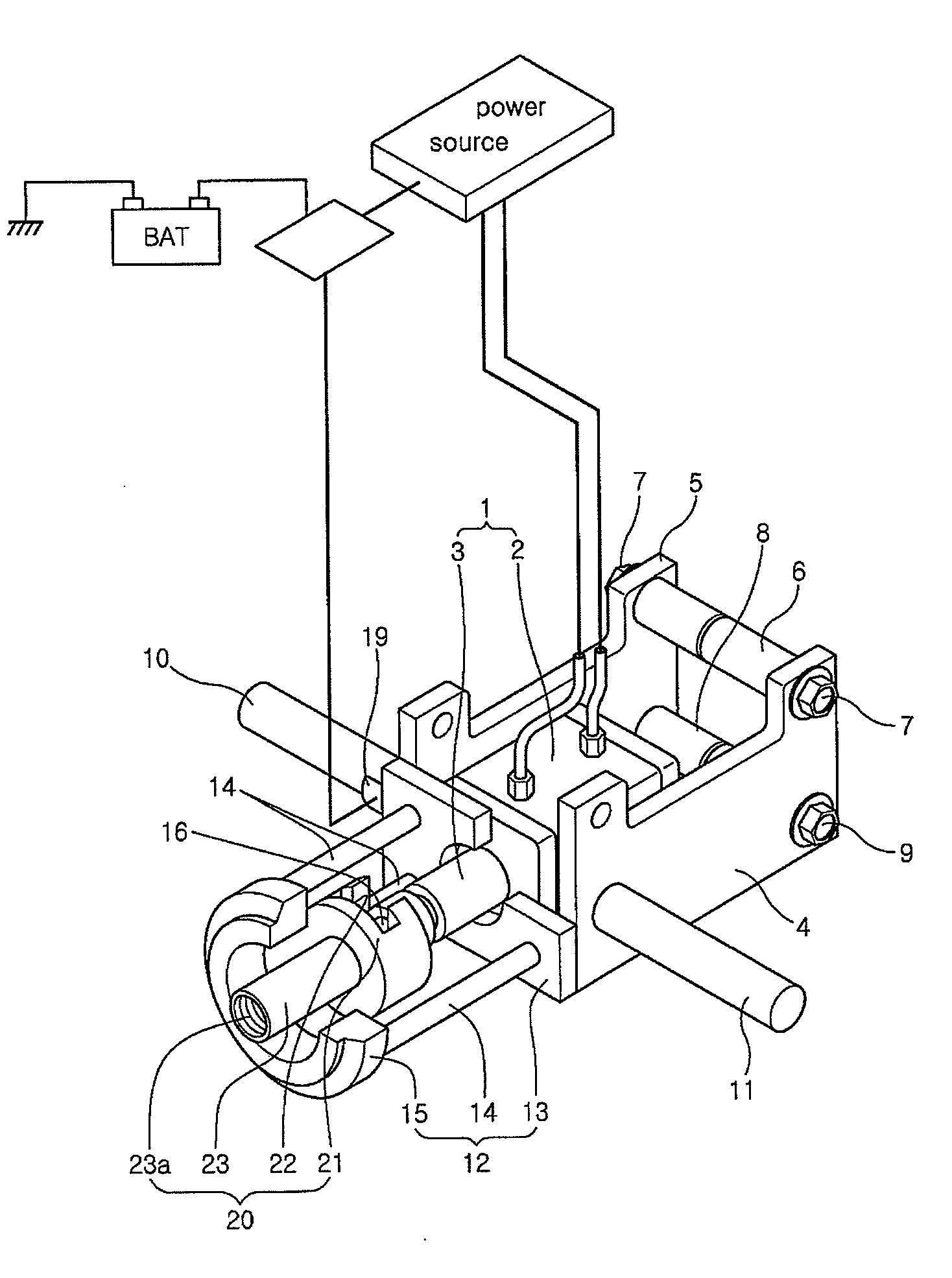
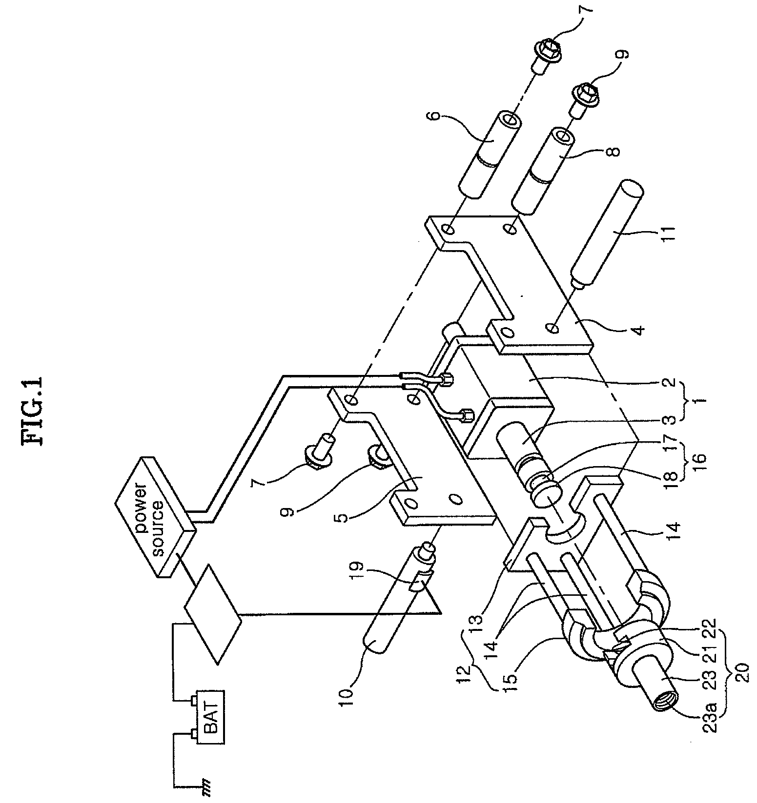
[0055]Supporting case 13 is combined with housing cases 4, 5 at both sides of driver 2 and has a through hole at the center in order not to interrupt the reciprocation of actuating rod 3 of driver 2.

[0056]Positioner 15 may have a variety of structures with a through hole at the center to allow the shaft-pulling member to axially move, but has a ring shape for uniform contact force to axle hub AH in this embodiment.

[0057]Since supporting member 12 restricts axle hub AH in axial pulling by close contact to axle hub AH, an interval should be maintained for close contact to axle hub AH. Therefore, the interval is determined in design of the jig assembly according to the length of supporting bars 14 of supporting member 12 or supporting bars 14 are threaded-fastened to supporting case 13 such that the length of supporting bars is variable.

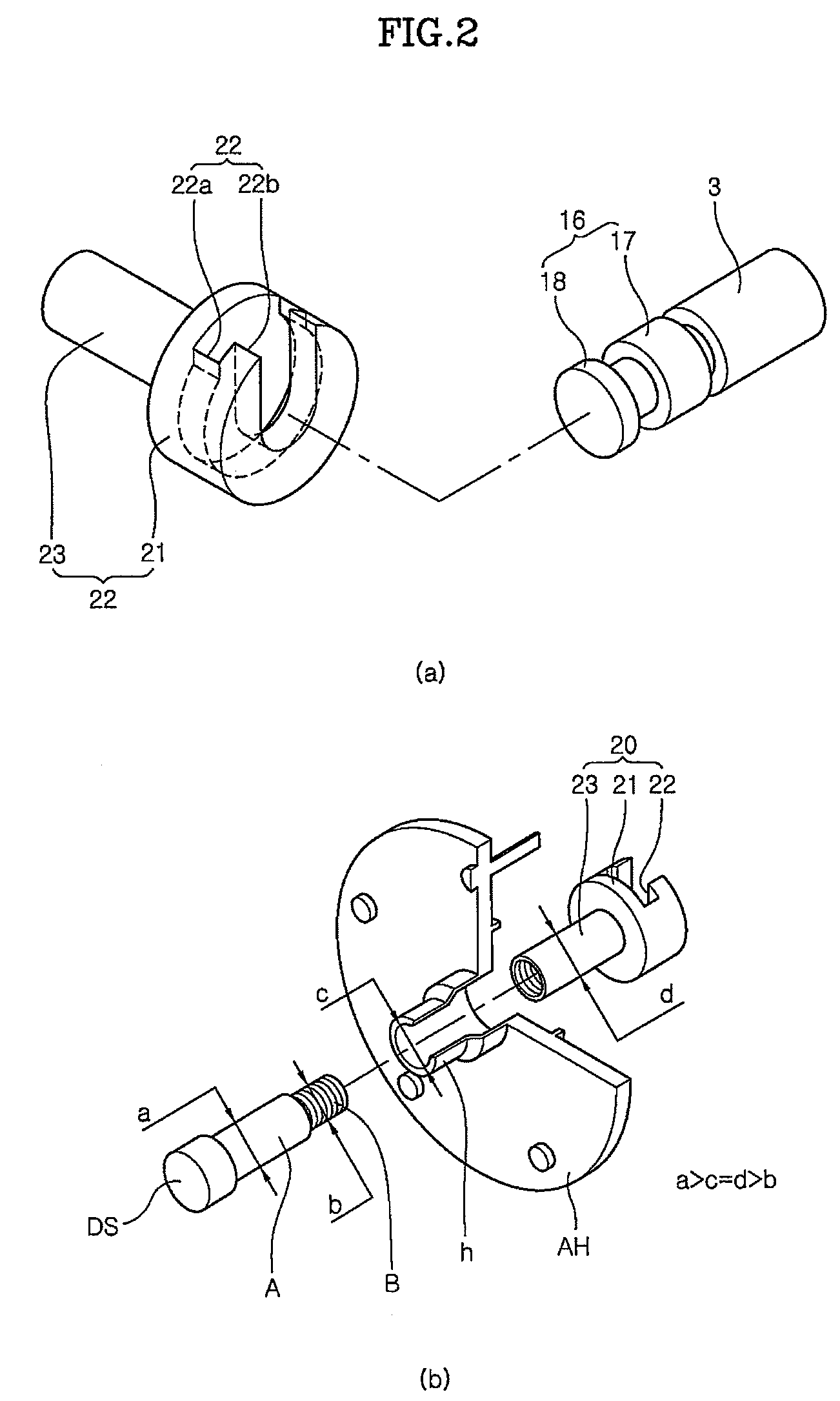
[0058]The shaft-pulling member includes a connecting end 16 that exerts pulling force by pulling of driver 2 in operation is connected to actuating rod...


PUM


Abstract

According to the present invention, a drive shaft DS is fitted into an axle hub AH with the drive shaft DS and a jig assembly arranged on an axis. Accordingly, a separate working place is not required because the fitting is performed in an assembly line where the components of a vehicle are assembled. Further, because the drive shaft DS is axially pulled, damage to peripheral parts of the axle hub AH, such as a constant velocity joint, is prevented. In addition, it is possible to set axial load of the drive shaft DS using a load cell, so that it can be applied to axial load between about 700 kgf and 1600 kgf.

Description

CROSS-REFERENCE TO RELATED APPLICATIONS[0001]The present application is based on, and claims priority from, Korean Application Serial Number 10-2007-0003310 and 10-2007-0065047, filed on Jan. 11, 2007 and Jun. 29, 2007, the disclosure of which is hereby incorporated by reference herein in its entirety.FIELD OF THE INVENTION[0002]The present invention relates to a pulling type drive shaft-fitting jig assembly, particularly a pulling type drive shaft-fitting jig assembly that fits a drive shaft into an axle hub while axially pulling the drive shaft.BACKGROUND OF THE INVENTION[0003]In general, driving torque that is generated by an engine and is converted by a transmission is transmitted to driving wheels through a driven reduction gear and a differential.[0004]Connected to the driving wheels to transmit the driving torque, the drive shaft is fitted in axle hubs of the driving wheels to transmit the driving force from the driven reduction gear and to withstand the load.[0005]The drivin...

Claims


Application Information

Patent Timeline
IPC IPC(8): F16D13/68
CPCF16D2300/12F16D1/06
Inventor LEE, GWUISEON
Owner HYUNDAI MOBIS CO LTD
Why Eureka
Try Eureka