Device for building a multilayer structure with storage container or filling container movable along the dispensing container

Active Publication Date: 2015-04-23
VOXELJET AG
View PDF5 Cites 121 Cited by
  • Summary
  • Abstract
  • Description
  • Claims
  • Application Information

AI Technical Summary

Benefits of technology

[0020]According to one refinement, the at least one outflow opening of the storage or filling container may be disposed at a level which essentially lies at a fill level to be attained for the free-flowing material in the discharge container, in order to close this at least one outflow opening at the current position of the at least one outflow opening on the discharge route upon reaching the fill level to be attained by the free-flowing material already introduced into the discharge container along a section of the discharge route already traveled. A so-called “material cone seal” is thus implemented, in which the material cone of the free-flowing material already discharged into the discharge container prevents further outflow at the current position of the discharge route through a buildup of material, and additional free-flowing material may flow out only when the storage and feed container [sic; storage and filling container] moves forward until the material cone again prevents the outflow at this position then

Problems solved by technology

However, such dosing-controlled and “intelligent” discharge containers have a relatively complex structure and are correspondingly expensive.
“Unintelligent” discharge containers of a simpler design, on the other hand, are unable to dose particulate material in a targeted manner or are not switchable.
This promotes the tendency of the sliding closure to become jammed.
In addition, a relatively large amount of energy must be expended to move the sliding closure.
To be able to move the hoses without kinking, the building device must have a certain height, which, however, causes the building device to have a large structural design

Method used


Image

  • Device for building a multilayer structure with storage container or filling container movable along the dispensing container
  • Device for building a multilayer structure with storage container or filling container movable along the dispensing container
  • Device for building a multilayer structure with storage container or filling container movable along the dispensing container

Examples


Example

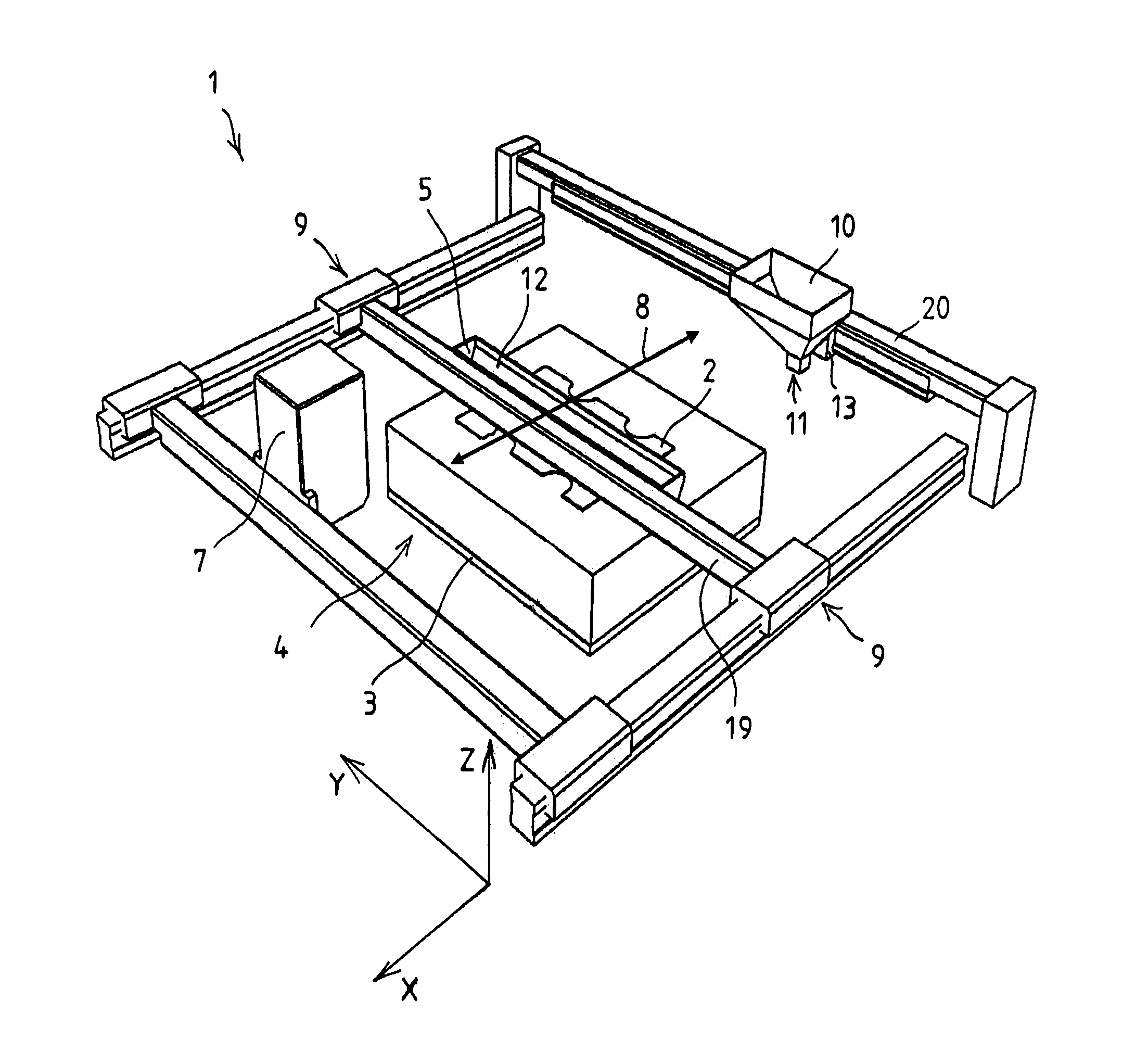
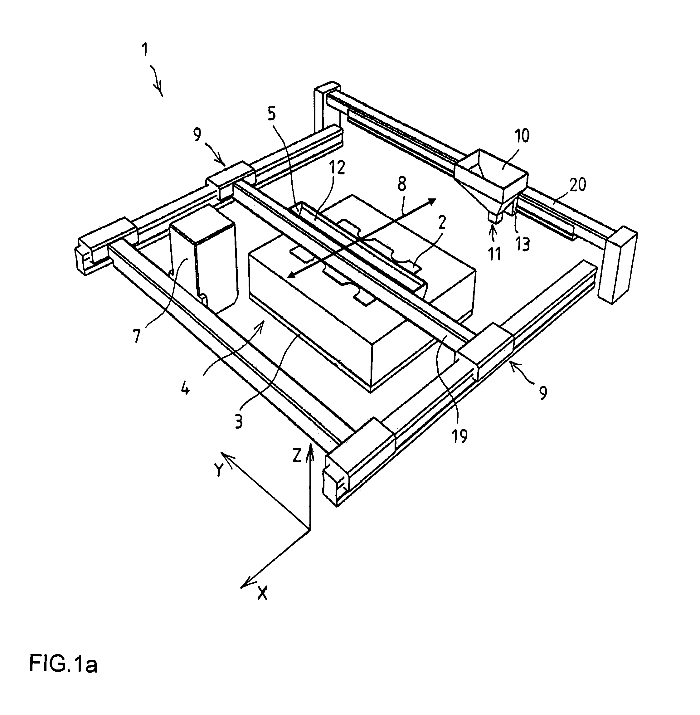
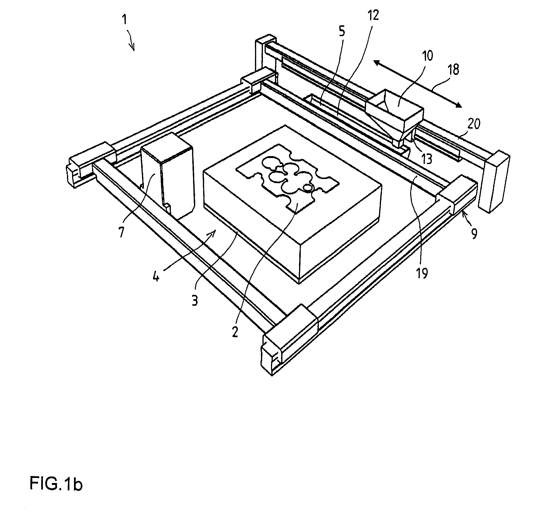
[0045]FIGS. 1a through 1c and FIGS. 2a and 2b, respectively, show a preferred embodiment of a device 1 for building a layer body or molding 2 from a plurality of superimposed layers of, for example powdered, initially loose, particulate material on a building platform 3 within a build space 4. Build space 4 illustrated in FIGS. 1a through 1c extends over a wide area in FIG. 1 parallel to building platform 3 in the horizontal X and Y directions, layer body 2 being built in the vertical Z direction.

[0046]Device 1 comprises a discharging device, which is movable back and forth over build space 4 in at least one discharge direction, in this case, for example, parallel to the X direction, and which includes a discharge container 5 which has a lower discharge opening 6, visible in FIG. 2a and FIG. 2b, from which the particulate material may be, discharged in individual superimposed layers during the movement of discharging device or discharge container 5. Discharge container 6 is attached...


PUM

PropertyMeasurementUnit
Lengthaaaaaaaaaa
Areaaaaaaaaaaa
Levelaaaaaaaaaa

Abstract

The invention relates to a device (1) for building a layer body (2) from a plurality of superimposed layers of free-flowing material, in particular particulate material, on a building platform (3) in a build space (4), the layers being solidified and joined to each other in locally predetermined areas, so that at least one layer body (2) is formed by the solidified and joined areas of the layers, including an elongated discharge container (5), which is movable back and forth over the build space (11 [sic; 4]) in at least one discharge direction and which has at least one discharge opening (6) from which the free-flowing material is dischargeable in individual superimposed layers during the movement of the discharge container (5), it being possible to supply the discharge container (5) with free-flowing material from a filling device with at least one storage or filling container (10) having at least one outflow opening (11) by vertically covering the at least one outflow opening (11) of the storage or filling container (10) with an elongated feed opening (12) of the discharge container (5).
The invention provides that the storage or filling container (10) has a shorter extension than the discharge container (5), viewed in the longitudinal direction of the discharge container (5), and the storage or filling container (10) is controllable relative to the discharge container (5), viewed in the longitudinal direction of the discharge container (5), in such a way that the outflow opening (11) of the storage or filling container (10) is guided along the feed opening (12) at least once from one end thereof to the other end thereof.

Description

BACKGROUND INFORMATION[0001]The invention relates to a device for building a layer body from a plurality of superimposed layers of free-flowing material, in particular particulate material, on a building platform in a build space, the layers being solidified and joined together in locally predetermined areas through the action of a binder, so that at least one molding is formed by the solidified and joined areas of the layers, including an elongated discharge container, which is movable back and forth over the build space in at least one discharge direction and which has at least one discharge>opening from which the free-flowing material is dischargeable in individual superimposed layers during the movement of the discharge container, it being possible to supply the discharge container with free-flowing material from a filling device with at least one storage or filling container having at least one outflow opening by vertically covering the at least one outflow opening of the st...

Claims


Application Information

Patent Timeline
IPC IPC(8): B29C67/00B22F3/00
CPCB29C67/0085B33Y30/00B22F3/003B29C64/153B29C64/165B29C64/255B29C64/205Y02P10/25B22F12/52B22F12/224B22F3/105B29C67/00
Inventor HARTMANN, ANDREAS DOMINIKSCHMID, DOMINIK
Owner VOXELJET AG
Why Eureka
Try Eureka