Methods and apparatus for passive thrust vectoring and plume deflection

Active Publication Date: 2015-04-30
THE BOEING CO
View PDF6 Cites 8 Cited by
  • Summary
  • Abstract
  • Description
  • Claims
  • Application Information

AI Technical Summary

Benefits of technology

[0009]An example method for vectoring exhaust gas air flow passing through a substantially annular exhaust bypass duct of a bypass jet engine is disclosed herein. The example method includes positioning a jet engine having a bypass duct beneath a wing such that unvectored jet exhaust flow from the bypass duct in a choked condition i

Problems solved by technology

Achieving in-flight thrust optimization with simultaneous minimization of exhaust jet (or flap) interaction and low

Method used


Image

  • Methods and apparatus for passive thrust vectoring and plume deflection
  • Methods and apparatus for passive thrust vectoring and plume deflection
  • Methods and apparatus for passive thrust vectoring and plume deflection

Examples


Embodiment Construction

[0035]Traditional fixed geometry approaches to achieving in-flight thrust optimization with simultaneous minimization of exhaust jet (or flap) interaction noise and low wing flap loading for fanjet engines have involved compromise where neither individual objective was fully achieved. An approach may be employed using variable geometry for thrust vectoring from the engine, but penalties may be incurred to propulsion system leakage and / or fuel burn, weight, complexity and / or failure modes, and maintenance, all of which burden the aircraft. Additionally, a variable geometry solution is costly to manufacture relative to a conventional design. No existing cost effective solutions are available for the problem without design compromises. Known designs point the nozzle flow in a single direction that is neither ideal for high speed cruise performance nor ideal for low speed community noise or wing flap structural weight. The result is non-optimum performance from both a fuel flow and nois...


PUM


Abstract

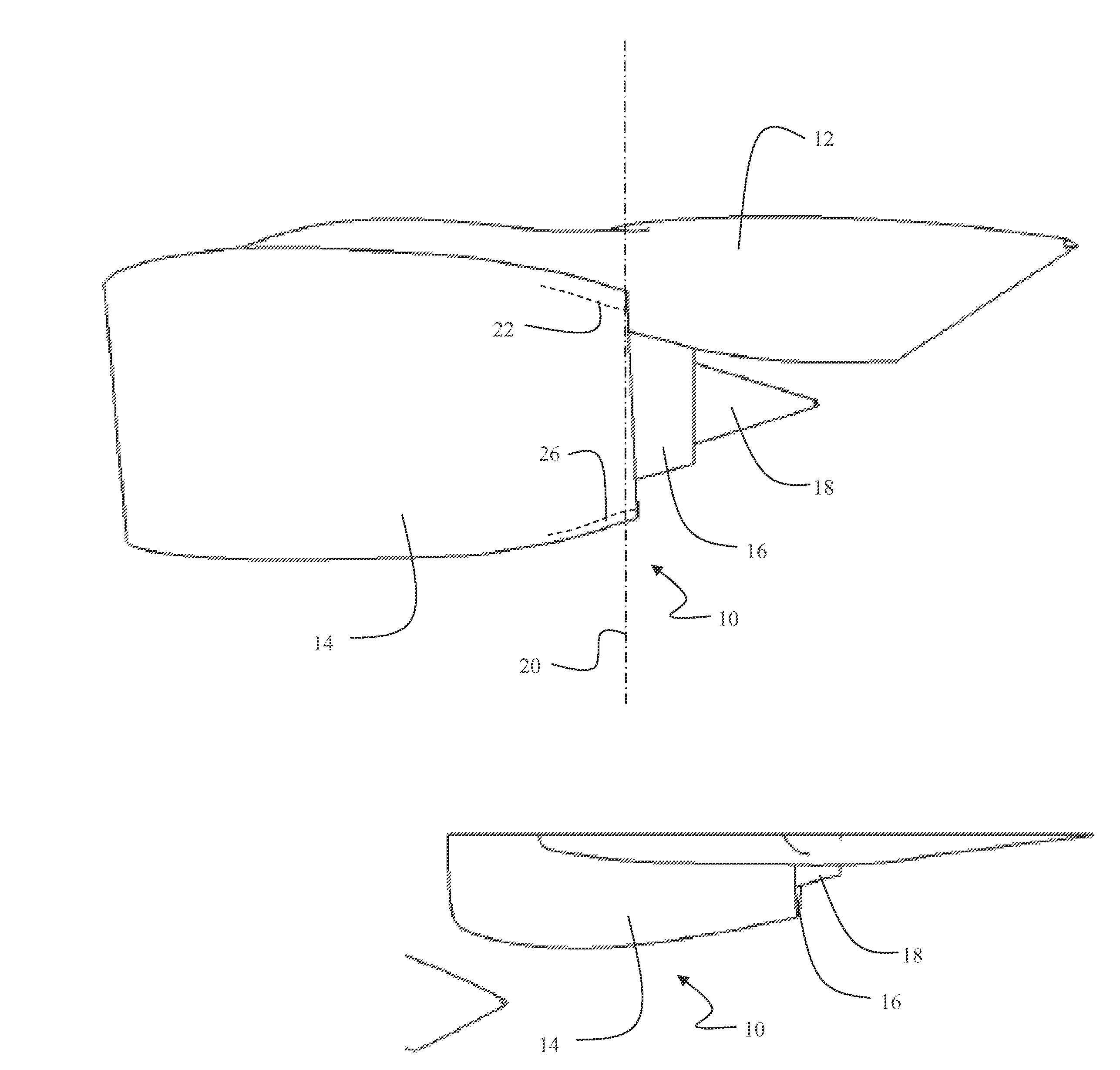
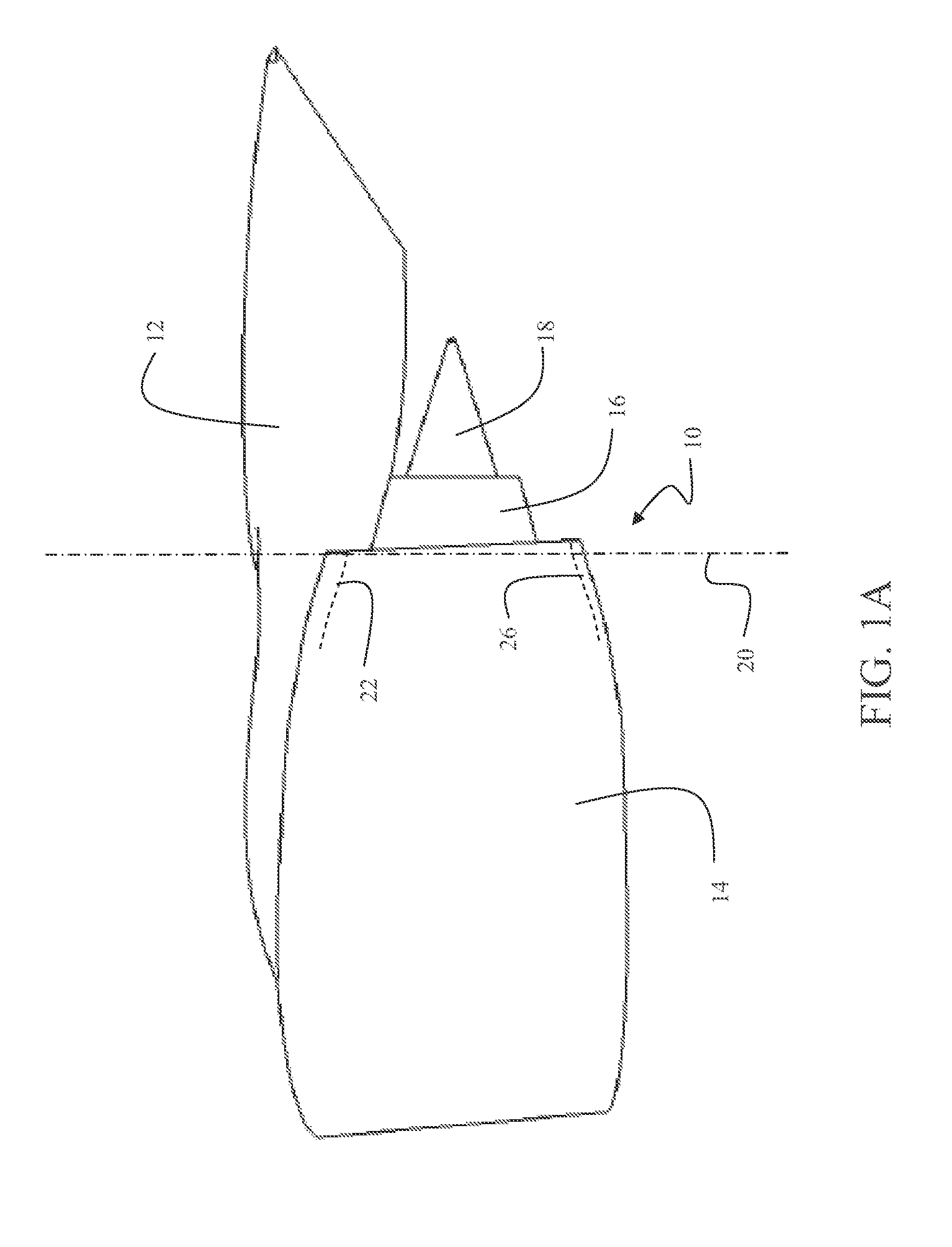
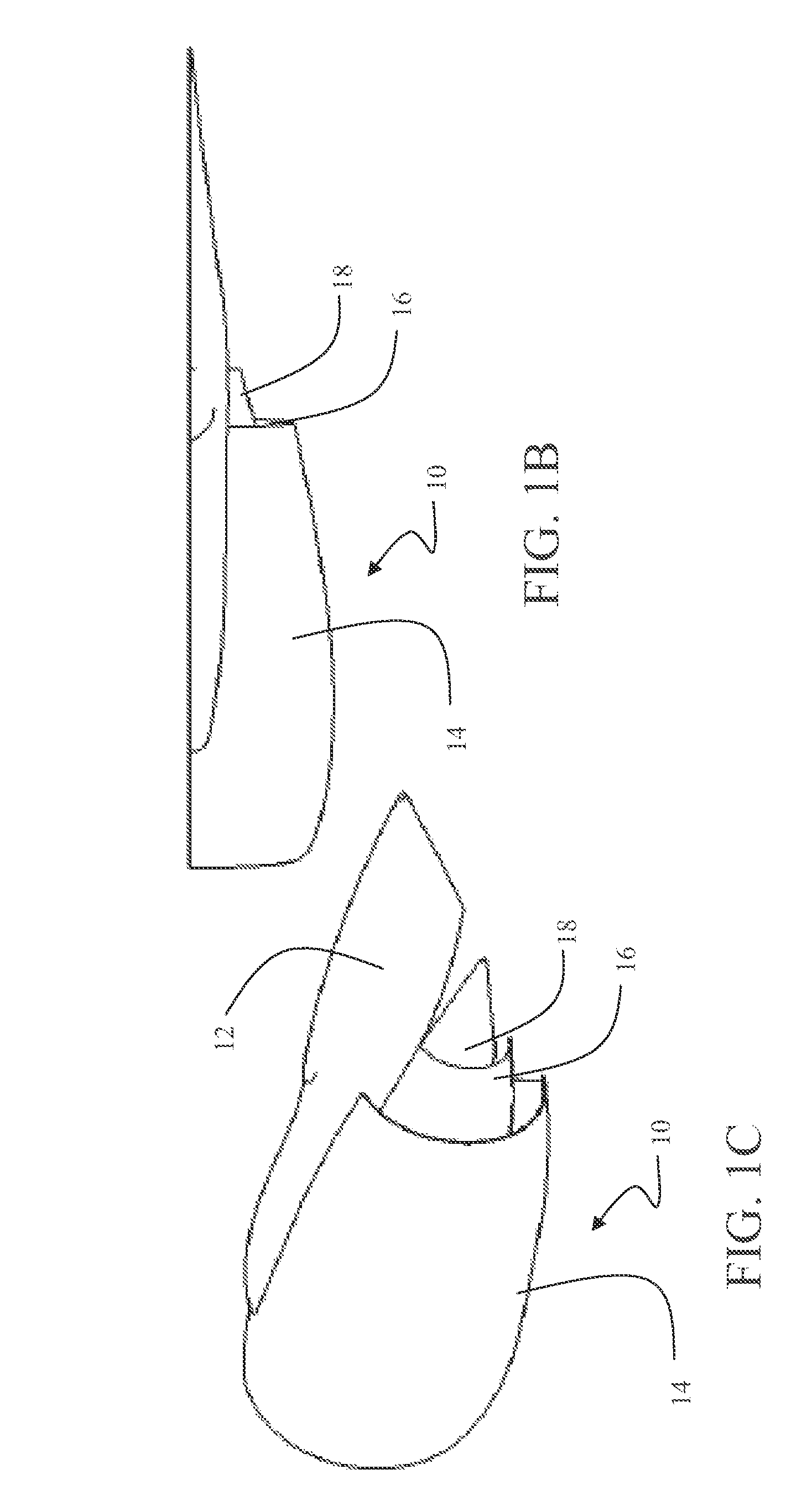
A flow vectoring turbofan engine employs a fixed geometry fan sleeve and core cowl forming a nozzle incorporating an asymmetric convergent/divergent (con-di) and/or curvature section which varies angularly from a midplane for reduced pressure in a first operating condition to induce flow turning and axially symmetric equal pressure in a second operating condition for substantially axial flow.

Description

BACKGROUND INFORMATION[0001]1. Field[0002]Embodiments of the disclosure relate generally to propulsion systems and, more particularly, to methods and apparatus for passive thrust vectoring and plume deflection.[0003]2. Background[0004]Achieving in-flight thrust optimization with simultaneous minimization of exhaust jet (or flap) interaction and low wing flap dynamic loading on an aircraft with a close coupled engine installation is a significant design challenge.SUMMARY[0005]An example flow vectoring turbofan engine disclosed herein includes a fixed geometry fan sleeve and core cowl forming a nozzle, the nozzle incorporating asymmetric convergence / divergence (con-di) and wall curvature varying angularly from a midplane, a first degree of the wall curvature being implemented during a first operating condition to reduce pressure, and a second degree of the wall curvature being implemented during a second operating condition to induce flow turning and axially symmetrically equal pressu...

Claims


Application Information

Patent Timeline
IPC IPC(8): F02K1/00
CPCF02K1/006F02K1/06F05D2250/323F05D2250/73F02K1/30F02K1/46F05D2250/71F05D2250/324Y02T50/60
Inventor WILLIE, ROBERT H.CERRA, DAVID F.HEBERT, LEONARD J.
Owner THE BOEING CO
Why Eureka
Try Eureka