

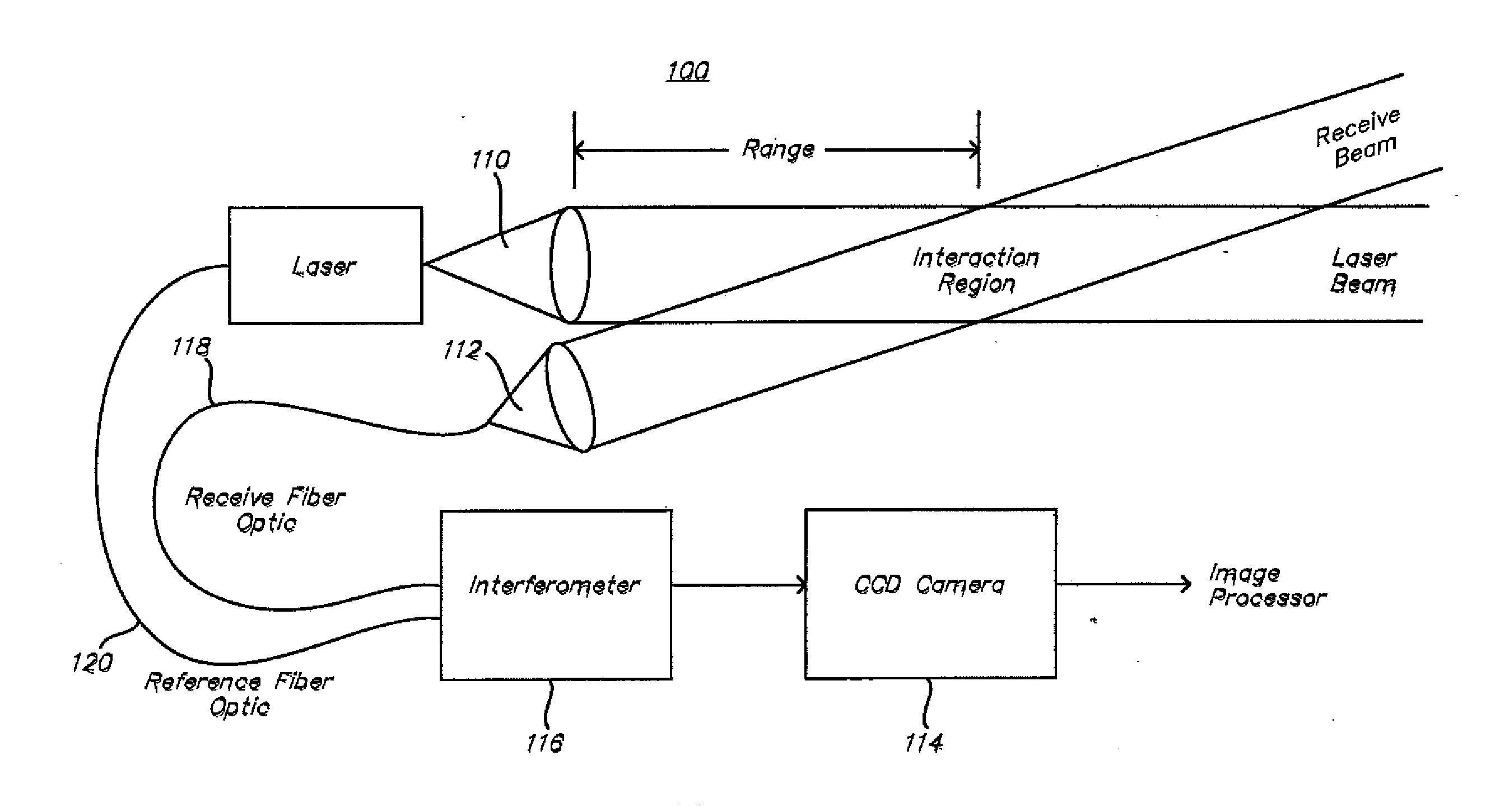
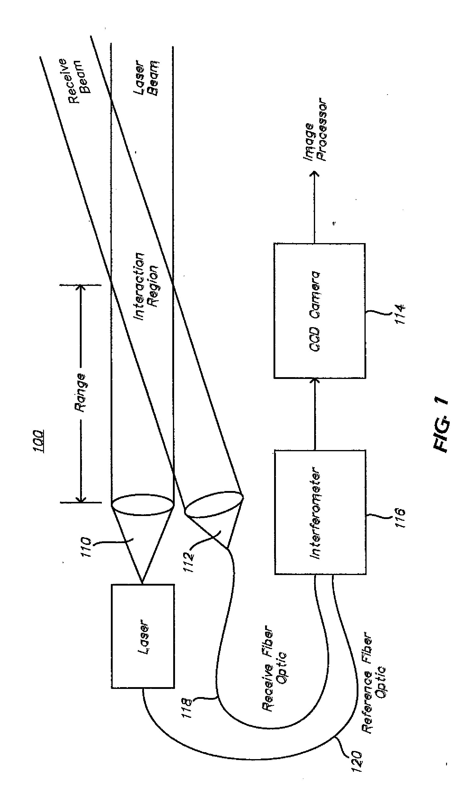
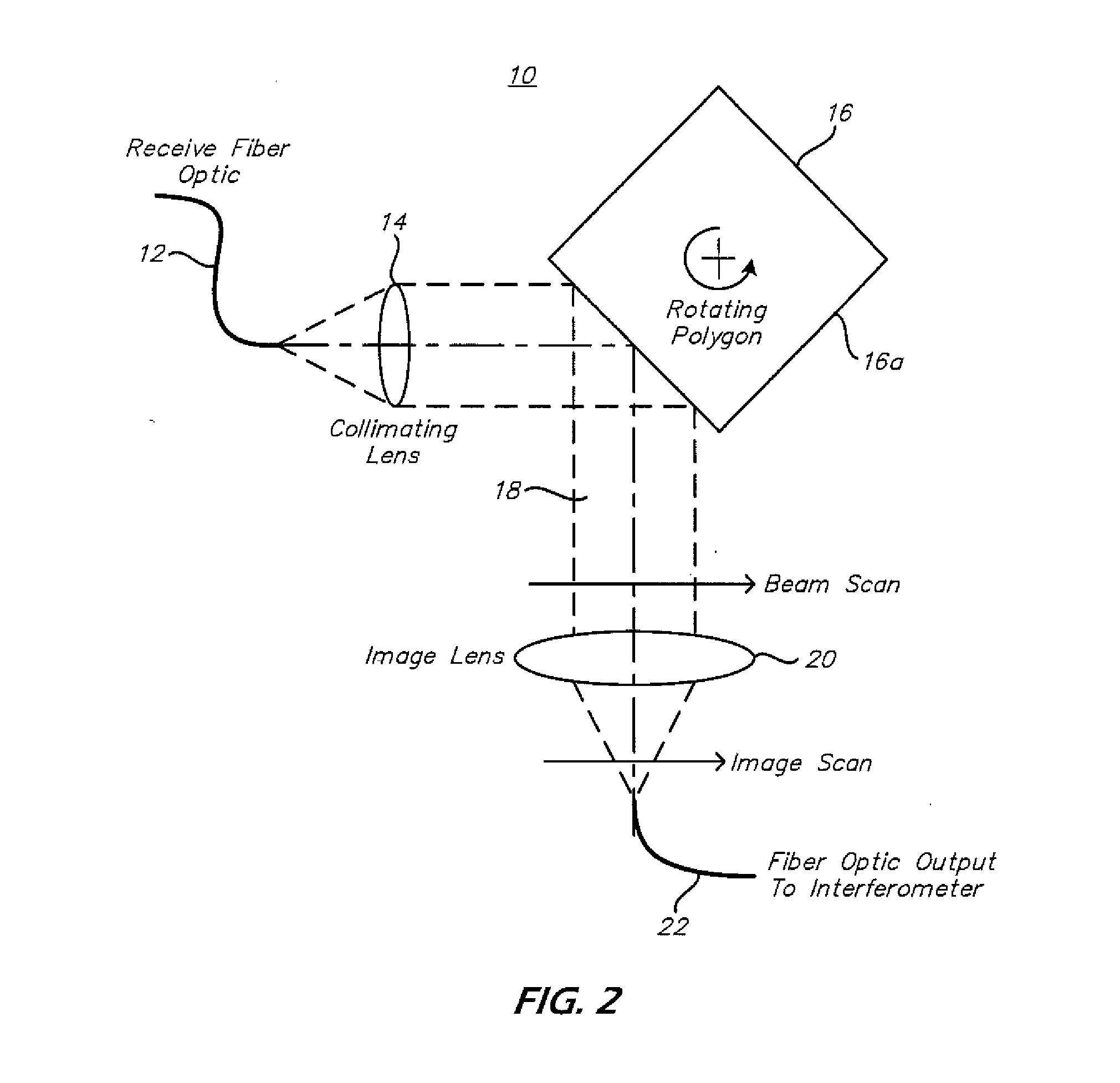
System and method for scan range gating
a technology of range gating and scanning method, which is applied in the field of range gating, can solve the problems of insufficient task and achieve the effect of improving measurement precision and large separation between source and receiver
- Summary
- Abstract
- Description
- Claims
- Application Information
AI Technical Summary
Benefits of technology
Problems solved by technology
Method used
Image

Examples
Embodiment Construction
[0032]While the specification concludes with claims defining the features of the invention that are regarded as novel, it is believed that the invention will be better understood from a consideration of the description of exemplary embodiments in conjunction with the drawings. It is of course to be understood that the embodiments described herein are merely exemplary of the invention, which can be embodied in various forms. Therefore, specific structural and functional details disclosed in relation to the exemplary embodiments described herein are not to be interpreted as limiting, but merely as a representative basis for teaching one skilled in the art to variously employ the present invention in virtually any appropriate form. For purposes of clarity, the same reference numbers will be used in the drawings to identify similar elements. Further, the terms and phrases used herein are not intended to be limiting but rather to provide an understandable description of the invention.
[00...
PUM
 Abstract
Description
Claims
Application Information