
Three-Dimensional Measuring Method And Surveying System

Active Publication Date: 2015-04-30
KK TOPCON
View PDF5 Cites 36 Cited by
  • Summary
  • Abstract
  • Description
  • Claims
  • Application Information

AI Technical Summary

Benefits of technology

The present invention provides a three-dimensional measuring method and a surveying system that can easily measure objects regardless of their complexity or the topography of the environment. The method involves using a total station with tracking function and a movable measuring device with a prism for retro-reflecting a distance measuring light and a tracking light projected from the total station. The total station measures the position of an object to be measured and the movable measuring device performs three-dimensional measurement on the object with reference to the total station. This allows for easy measurement at any position, without the need for a change in the installation of the total station. The surveying system also includes an arithmetic control part that combines the results of the total station and the movable measuring device, allowing for seamless and accurate three-dimensional measurement. Overall, the invention provides a reliable and efficient solution for carrying out three-dimensional measurement in various settings.

Problems solved by technology

For this reason, there are many restrictions in the place of installation, and further, in a case where a dead area is present for the measurement of an object to be measured, the changing of the installation of the measuring instrument is necessary.
Further, in a case where the object to be measured is a construction object with complicated structure, there may be many portions which cannot be measured due to a problem of a poor field of vision.
For this reason, there are problems in that the more complicated the construction object is, the more complicated the working process becomes.
However, there have been problems in that the coordinates cannot be determined or that there are many cases which are complicated.

Method used


Image

  • Three-Dimensional Measuring Method And Surveying System
  • Three-Dimensional Measuring Method And Surveying System
  • Three-Dimensional Measuring Method And Surveying System

Examples


Embodiment Construction

[0025]Description will be given below on an embodiment of the present invention by referring so the attached drawings.

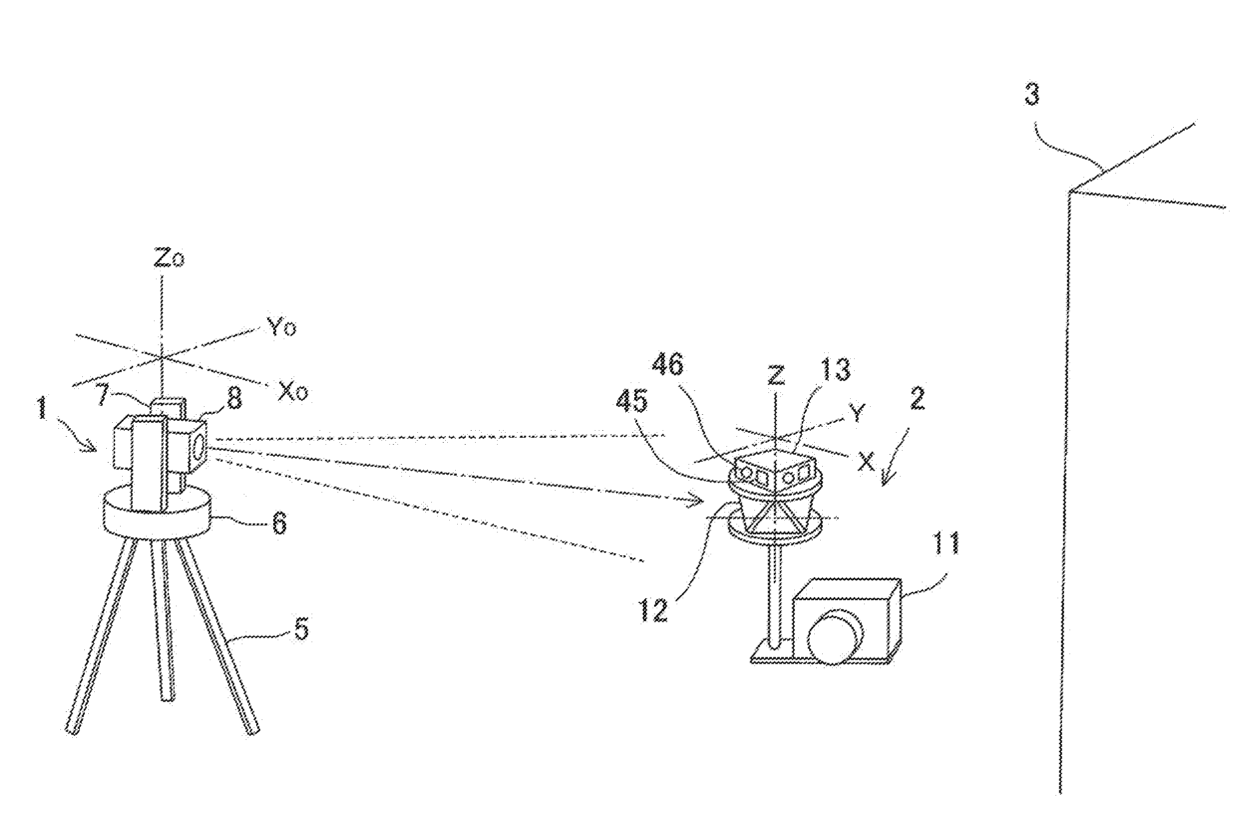
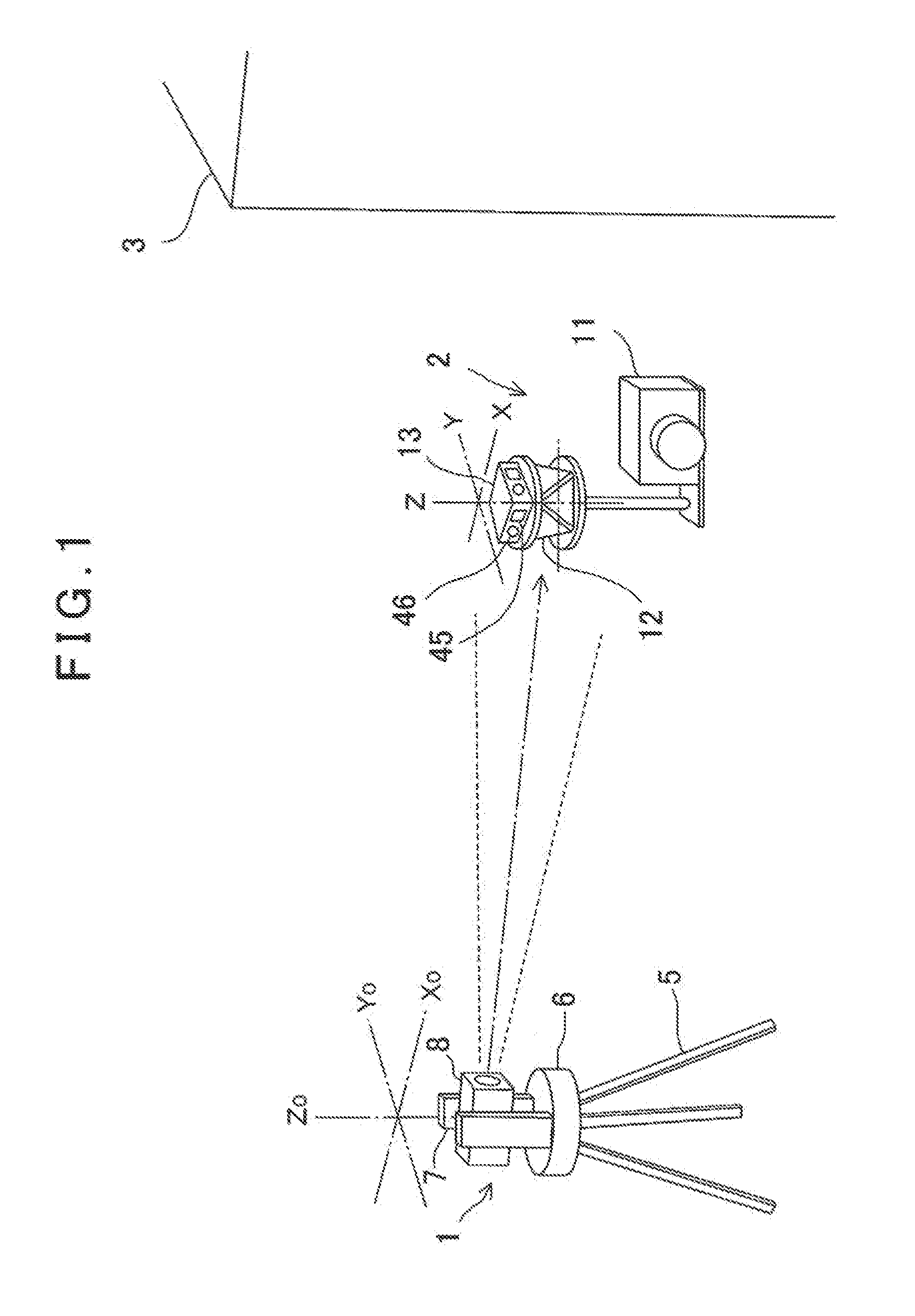
[0026]First, by referring to FIG. 1, description will be given below on general features of an embodiment according to the present invention.

[0027]In the figure, reference numeral 1 denotes a total station used as a main surveying device. Reference numeral 2 denotes a movable measuring device used as an auxiliary surveying device and reference numeral 3 denotes an object to be measured. It is to be noted that the total station 1 is a surveying instrument which can measure a distance, a horizontal angle and a vertical angle of a measuring point. Further, in the present invention, the surveying instrument has a tracking function.

[0028]The total station 1 is installed at a known position. It is to be noted that the installation position of the total station 1 may be already known as absolute coordinates or may be already known as relative coordinates with respect to the...


PUM


Abstract

The invention provides a surveying system comprising a total station installed at a known point and having a tracking function, at least one movable measuring device having a prism for retro-reflecting a distance measuring light and a tracking light projected from the total station and capable of moving and of performing three-dimensional measurement on an object to be measured and an arithmetic control part, wherein the movable measuring device has an auxiliary measuring unit capable of measuring a distance and an angle of the object to be measured and an attitude detector capable of detecting a measuring direction, a tilting and a tilting direction of the movable measuring device, wherein the movable measuring device performs three-dimensional measurement on the object to be measured with reference to direction of the total station based on the measurement result of the auxiliary measuring unit and on the detection result of the attitude detector at an arbitrary measurement position as being sighted from the total station, wherein the total station performs three-dimensional measurement on the measurement position, and wherein the arithmetic control part performs three-dimensional measurement on the object to be measured with reference to the total station based on the result of three-dimensional measurement obtained by the movable measuring device and on the measurement result by the total station.

Description

BACKGROUND OF THE INVENTION[0001]The present invention relates to a three-dimensional measuring method and a surveying system, which has a simple configuration and which can perform three-dimensional measurement over a wide range.[0002]Conventionally, for three-dimensional (hereinafter referred as “3D”) measurement of a construction object, a total station or a 3D scanner is used. However, a measuring instrument as such is designed to measure a distance by projecting a distance measuring light and by receiving a reflected distance measuring light. In this respect, it is necessary that an entire measurement area can be overlooked from a point of installation of the measuring instrument. For this reason, there are many restrictions in the place of installation, and further, in a case where a dead area is present for the measurement of an object to be measured, the changing of the installation of the measuring instrument is necessary.[0003]Further, in a case where the object to be meas...

Claims


Application Information

Patent Timeline
IPC IPC(8): G01C15/00G01S17/66G01S17/42
CPCG01C15/002G01S17/66G01S17/42G01C15/00
Inventor OHTOMO, FUMIOKUMAGAI, KAORUOTANI, HITOSHIOSARAGI, KAZUKI
Owner KK TOPCON
Features
  • Generate Ideas
  • Intellectual Property
  • Life Sciences
  • Materials
  • Tech Scout
  • Unparalleled Data Quality
  • Higher Quality Content
  • 60% Fewer Hallucinations
Learn More