Magnetic stirrer with a temperature measuring device

a temperature measurement device and magnetic stirrer technology, applied in the direction of level indicators by physical variable measurement, mixers, instruments, etc., can solve the problems of temperature and also different fill levels in such containers, and cannot be detected by the temperature measuring devi

Active Publication Date: 2015-04-30
IKA WERKE
View PDF14 Cites 10 Cited by
  • Summary
  • Abstract
  • Description
  • Claims
  • Application Information

AI Technical Summary

Benefits of technology

[0005]To solve this problem, it is proposed that the temperature measuring device has at least three temperature sensors which can be dipped into the medium being measured in the position of use and which are arranged at different heights and / or with a vertical spacing from each other. In this way, it is possible to detect the temperature of the medium during the heating with only one temperature measuring device at different intervals from the heating plate. Since the heating generally starts from the bottom on account of the heating plate arranged underneath the container or beaker in the usage position and accordingly the temperature within the medium decreases from bottom to top, it is possible to identify a temperature stratification or a temperature distribution within the container especially during the heating of the medium, but also in the further operation, with the help of the temperature measuring device.

Problems solved by technology

However, very different temperatures and also different fill levels can occur in such a container, which cannot be detected by the temperature measuring device thus far.
Therefore, the problem exists of creating a magnetic stirrer of the kind mentioned at the outset, with which the temperature and the temperature distribution of the medium can be measured more accurately.

Method used


Image

  • Magnetic stirrer with a temperature measuring device
  • Magnetic stirrer with a temperature measuring device
  • Magnetic stirrer with a temperature measuring device

Examples


Embodiment Construction

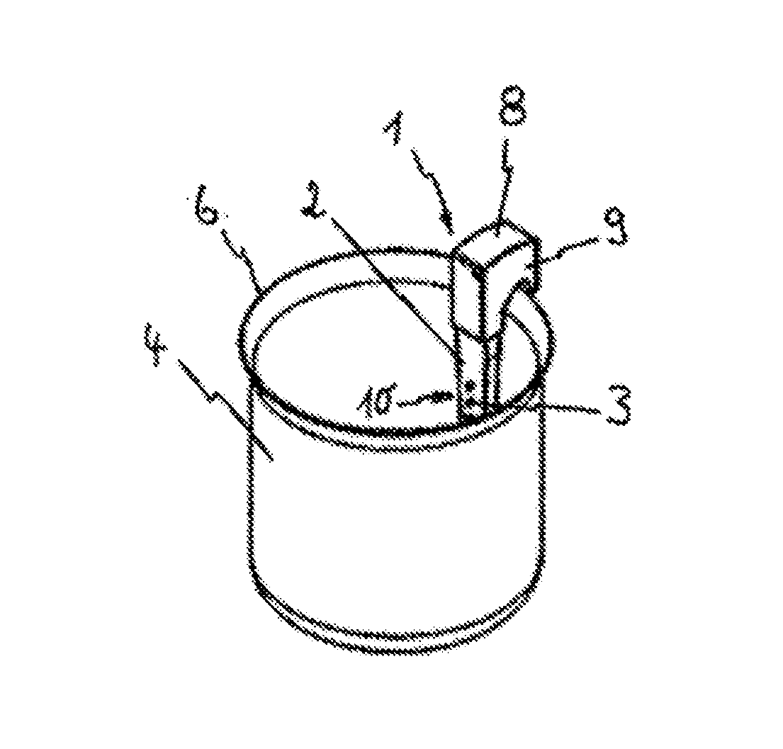
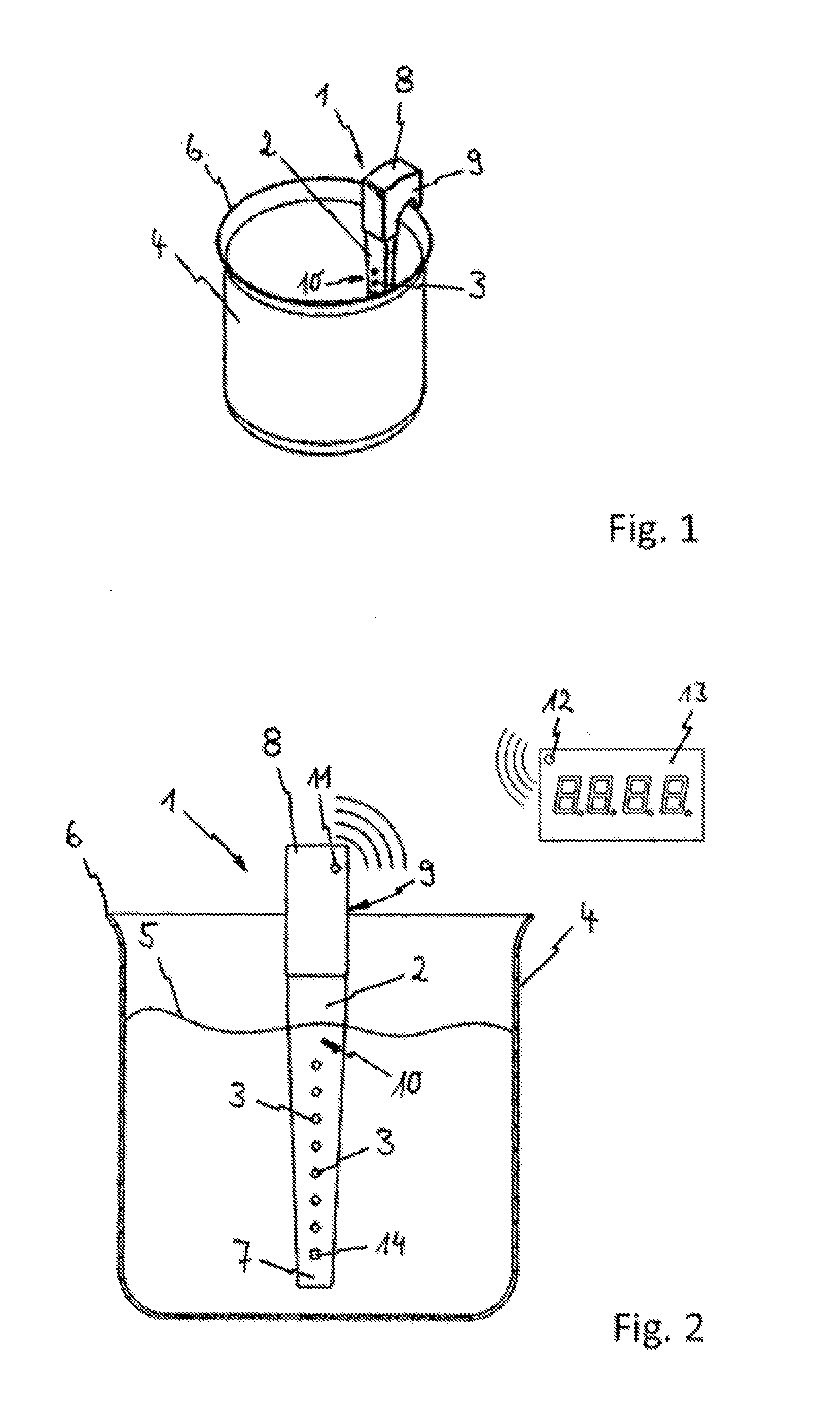
[0030]A temperature measuring device designated overall as 1 has, according to the figures, a thermometer 2 with several temperature sensors 3 on an electrical basis. FIG. 1 shows the temperature measuring device 1 in its position of use in a container or beaker 4. According to FIG. 2 and FIG. 4 the beaker 4 contains a liquid medium 5, in which medium 5 the temperature sensors 3 of the temperature measuring device 1 are dipped.

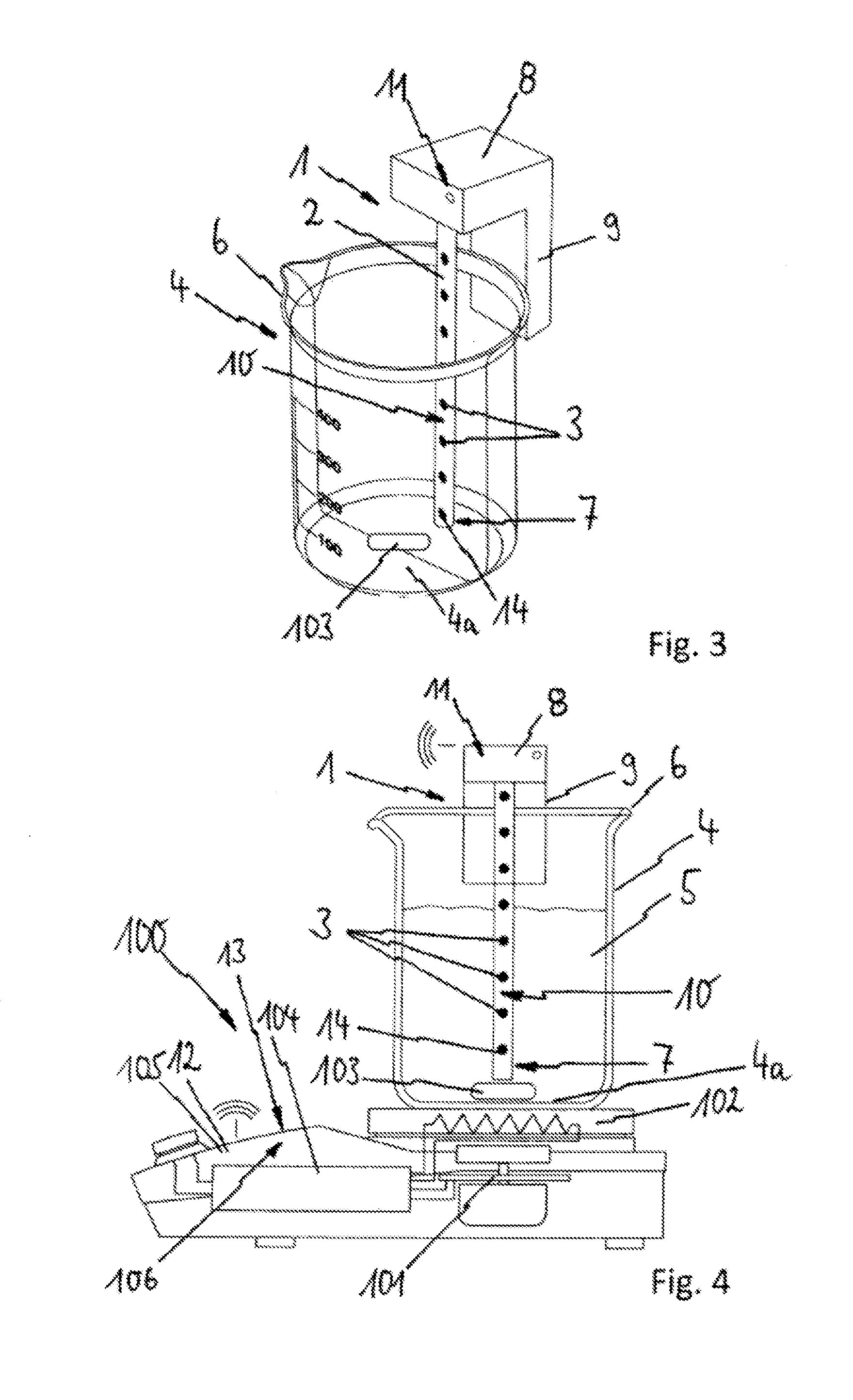
[0031]In order to heat the medium 5 inside the container 4, the container 4 can be placed on a heating plate 102 of a magnetic stirrer 100, represented in FIG. 4. For the stifling of the medium 5, the magnetic stirrer 100 will drive the one stifling magnet 103 situated in the container 4 in the position of use via a rotary magnetic field generated by a stirring drive unit 101 of the magnetic stirrer 100.

[0032]The temperature sensors 3 are arranged at different heights and with vertical spacing from each other on the temperature measuring device 1. The vertical...


PUM


Abstract

A temperature measuring device (1) with a thermometer (2) has a plurality of temperature sensors (3) on one side (10), which function on an electrical basis. The thermometer (2) is immersed in a container or beaker (4) set up in a usage position on a heating plate (102) of a magnetic stirrer (100) and in a medium (5) present therein. The plurality of temperature sensors (3) are arranged spaced apart from one other vertically on the temperature measuring device (1), and are immersed in the medium (5) at different heights in the usage position. It is therefore possible firstly to recognize a temperature stratification inside the medium (5), and secondly, to detect level changes of the medium (5) in the interior of the container (4).

Description

BACKGROUND OF THE INVENTION[0001]The invention concerns a magnetic stirrer with a stirring drive unit, with a container or beaker, with a heating plate as a support surface for the container or beaker, and with a stirring magnet which can be inserted into the container or beaker and driven by the stirring drive unit, and with a temperature measuring device with a thermometer having a temperature sensor operating on an electrical basis, which is dipped or can be dipped into the medium located in the container or beaker.[0002]Such a magnetic stirrer with a temperature measuring device is already known from DE 33 42 249 C2, where a change in temperature of the medium located in the container or beaker can be measured with the temperature measuring device.[0003]However, very different temperatures and also different fill levels can occur in such a container, which cannot be detected by the temperature measuring device thus far.[0004]Therefore, the problem exists of creating a magnetic s...

Claims


Application Information

Patent Timeline
Patent Type & Authority Applications(United States)
IPC IPC(8): B01F13/08B01F15/00B01F15/06
CPCB01F13/0818B01F15/065B01F2015/062B01F15/00175B01F15/00389G01K1/026G01F23/22G01K2213/00B01F33/452B01F35/2212B01F35/2215B01F35/92B01F2101/23B01F35/2115B01F35/221422B01F2035/99
Inventor EBLE, ERHARDBRAUCH, UWEHENSLE, THOMASBABEL, CHRISTIAN
Owner IKA WERKE
Why Eureka
Try Eureka