Eureka AIR delivers breakthrough ideas for toughest innovation challenges, trusted by R&D personnel around the world.

Systems and methods for on-chip temperature sensor

Inactive Publication Date: 2015-04-30
MAXIM INTEGRATED PROD INC
View PDF10 Cites 22 Cited by
  • Summary
  • Abstract
  • Description
  • Claims
  • Application Information

AI Technical Summary

Benefits of technology

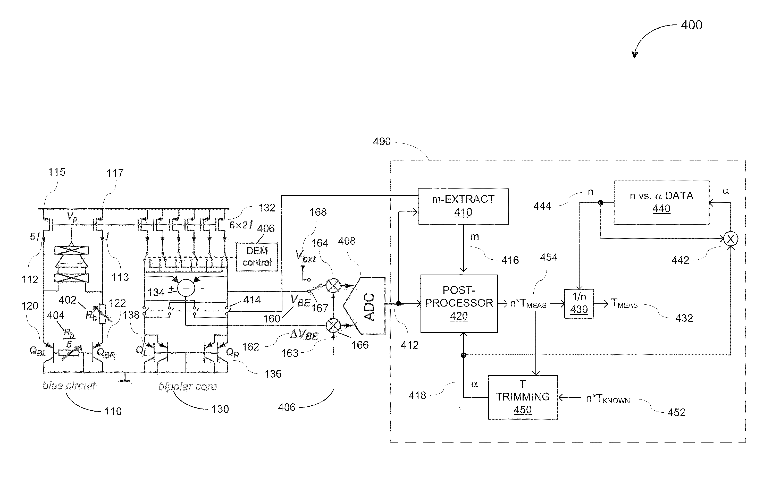
The patent text describes systems and methods to reduce temperature measurement errors in on-chip temperature sensors caused by two non-idealities: mismatch in reverse saturation current and process-dependent injection factor error. The invention uses a circuit to digitally process VBE signals and reverses the inputs of BJTs to perform averaging. Additionally, calibration parameters are computed for individual samples to eliminate the need for precise temperature sensors and de-embed the effects of non-idealities while taking advantage of known variations in injection factor with process. The technical effects of the invention are reduced temperature measurement errors and improved accuracy of temperature sensors.

Problems solved by technology

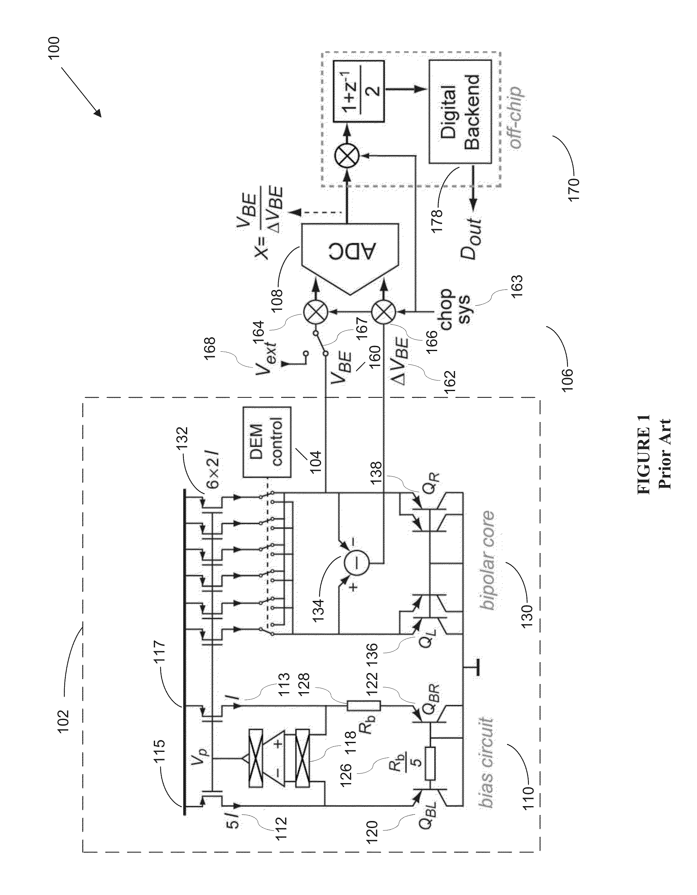
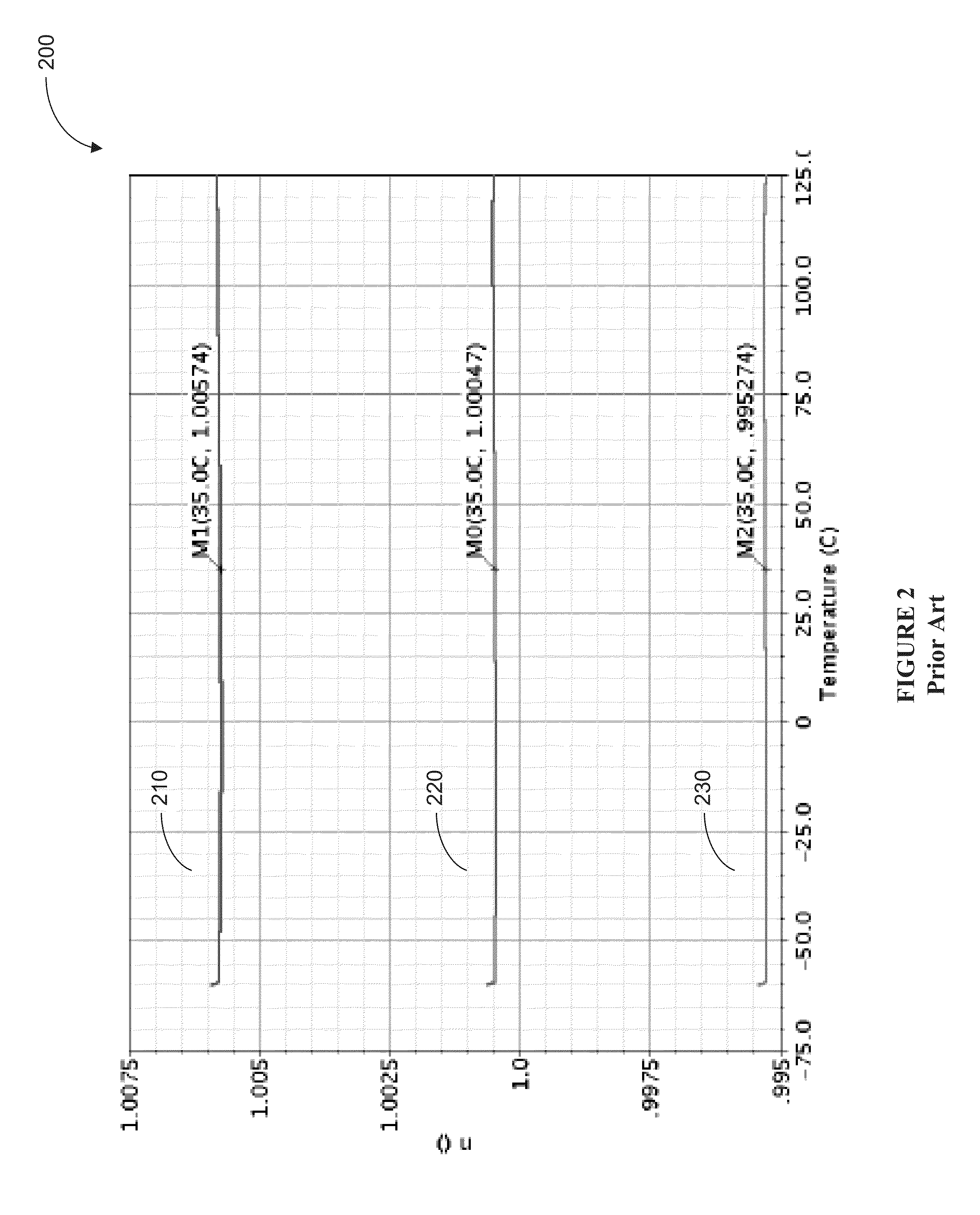
However, when compensating error amplifier offset, current mirroring ratio error, and finite beta effects in the analog domain, additional non-idealities are associated with temperature sensing, including but may not be limited to mismatch in the reverse saturation currents of the two BJT's and process-dependent injection factor errors.
The mismatch in the reverse saturation currents of the BJT's is oftentimes compensated using continuous switching of the BJT's which may not be power efficient, while process-dependent injection factor errors are corrected incompletely using a batch calibration method that results in a rather non-optimal accuracy.
Batch calibration additionally requires a precision temperature sensor of known accuracy, which not only increases cost but also testing time due to the additional time required for the junction temperature to settle.

Method used


Image

  • Systems and methods for on-chip temperature sensor
  • Systems and methods for on-chip temperature sensor
  • Systems and methods for on-chip temperature sensor

Examples


Embodiment Construction

[0023]In the following description, for the purpose of explanation, specific details are set forth in order to provide an understanding of the invention. It will be apparent, however, to one skilled in the art that the invention can be practiced without these details. One skilled in the art will recognize that embodiments of the present invention, described below, may be performed in a variety of ways and using a variety of means. Those skilled in the art will also recognize that additional modifications, applications, and embodiments are within the scope thereof, as are additional fields in which the invention may provide utility. Accordingly, the embodiments described below are illustrative of specific embodiments of the invention and are meant to avoid obscuring the invention.

[0024]Reference in the specification to “one embodiment” or “an embodiment” means that a particular feature, structure, characteristic, or function described in connection with the embodiment is included in ...


PUM


Abstract

Various embodiments of the invention use the characteristics of BJTs to compute parameter values required to de-embed the effects of non-idealities including BJT's-mismatch in the reverse saturation current and process-dependent injection factor. In some embodiments, a temperature sensor circuit and method provide high temperature accuracy in a low-cost way by individually calibrating each part, thereby, eliminating the need to accurately measure temperature with a precision temperature sensor.

Description

CROSS-REFERENCE TO RELATED APPLICATIONS[0001]This application claims priority to India Patent Application No. 3413 / MUM / 2013, filed Oct. 29, 2013, entitled, “Systems and Methods for On-Chip Temperature Sensor,” which application is hereby incorporated herein by reference in its entirety.BACKGROUND[0002]A. Technical Field[0003]The present invention relates to low power temperature sensors and, more particularly, to systems, devices, and methods of accurately measuring on-chip temperature with solid-state junction temperature sensors.[0004]B. Background of the Invention[0005]Embedded on-chip temperature sensors are becoming increasingly critical in today's electronic devices. Security and medical device applications, in particular, have stringent requirements for accurate, low-power on-chip temperature monitoring. BJT-based temperature sensors provide extreme low-power solutions. Some existing BJT-based sensors take advantage of the fact that the quantity VBE / ΔVBE of a set of bipolar t...

Claims


Application Information

Patent Timeline
IPC IPC(8): G01K7/00G01K15/00
CPCG01K15/005G01K7/006G01K7/01
Inventor TIRUVURU, RAJESHKARANAM, KRISHNA MAHESHJOHARAPURKAR, ASHUTOSHKWAK, SUNG UNG
Owner MAXIM INTEGRATED PROD INC
Why Eureka
Eureka Blog
Learn More