Exhaust-gas aftertreatment device and associated production method

Active Publication Date: 2015-05-07
PUREM GMBH
View PDF6 Cites 7 Cited by
  • Summary
  • Abstract
  • Description
  • Claims
  • Application Information

AI Technical Summary

Benefits of technology

This patent describes a way to calibrate the size of a jacket used in a fuel injector system. The calibration ensures that the jacket has a constant outer size along its entire length, even in the region where the ends of the jacket are connected to other components. This makes the calibration process simpler than usual, as it can be done using a conventional tool. The patent also suggests a way to achieve a uniform compression of a bearing mat used in the system, even in the regions where the jacket has a smaller radius. Additionally, the patent mentions a way to create a radial preload between the jacket and the connecting regions, which helps to ensure the proper functioning of the fuel injector system.

Problems solved by technology

However, ceramic materials are comparatively brittle and have a thermal expansion coefficient which significantly differs from the thermal expansion coefficients of metals, which are usually employed for producing the housing.
A further problem when using ceramic monoliths is production-related.
Furthermore, the aggressive hot exhaust gases during the operation of the exhaust gas aftertreatment device can attack and destabilize the bearing mat.
If by contrast the compression is too severe, the bearing mat can no longer elastically absorb the thermal expansion effects, as a result of which the lifespan of the mounting or the retaining of the monolith in the housing is likewise greatly impaired.
Additionally, the permissible stresses can then be exceeded on the monolith as a result of which the risk of damaging the monolith also arises.
During pre-sizing, introducing the monolith with the bearing mat in the housing is comparatively complex since during the axial insertion comparatively large shearing forces act on the bearing mat, as a result of which damages to the bearing mat can occur.
Since the jacket through the calibrating can have varying cross sections, further problems for attaching the funnels arise since standard funnels are too large as a rule and weld seams are comparatively unstable for offsetting these dimensions.
Because of this, new problems are created however since with plugged-in funnel the respective connecting section of the funnel then axially enters the ring gap between monolith and jacket, which impairs the installation space that is available for the bearing mat.
There is thus the risk altogether that the bearing mat can no longer optimally fulfill its retaining function.

Method used


Image

  • Exhaust-gas aftertreatment device and associated production method
  • Exhaust-gas aftertreatment device and associated production method
  • Exhaust-gas aftertreatment device and associated production method

Examples


Embodiment Construction

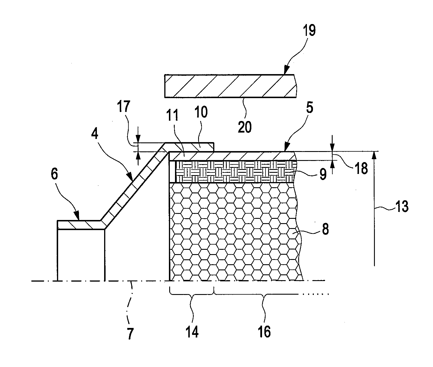
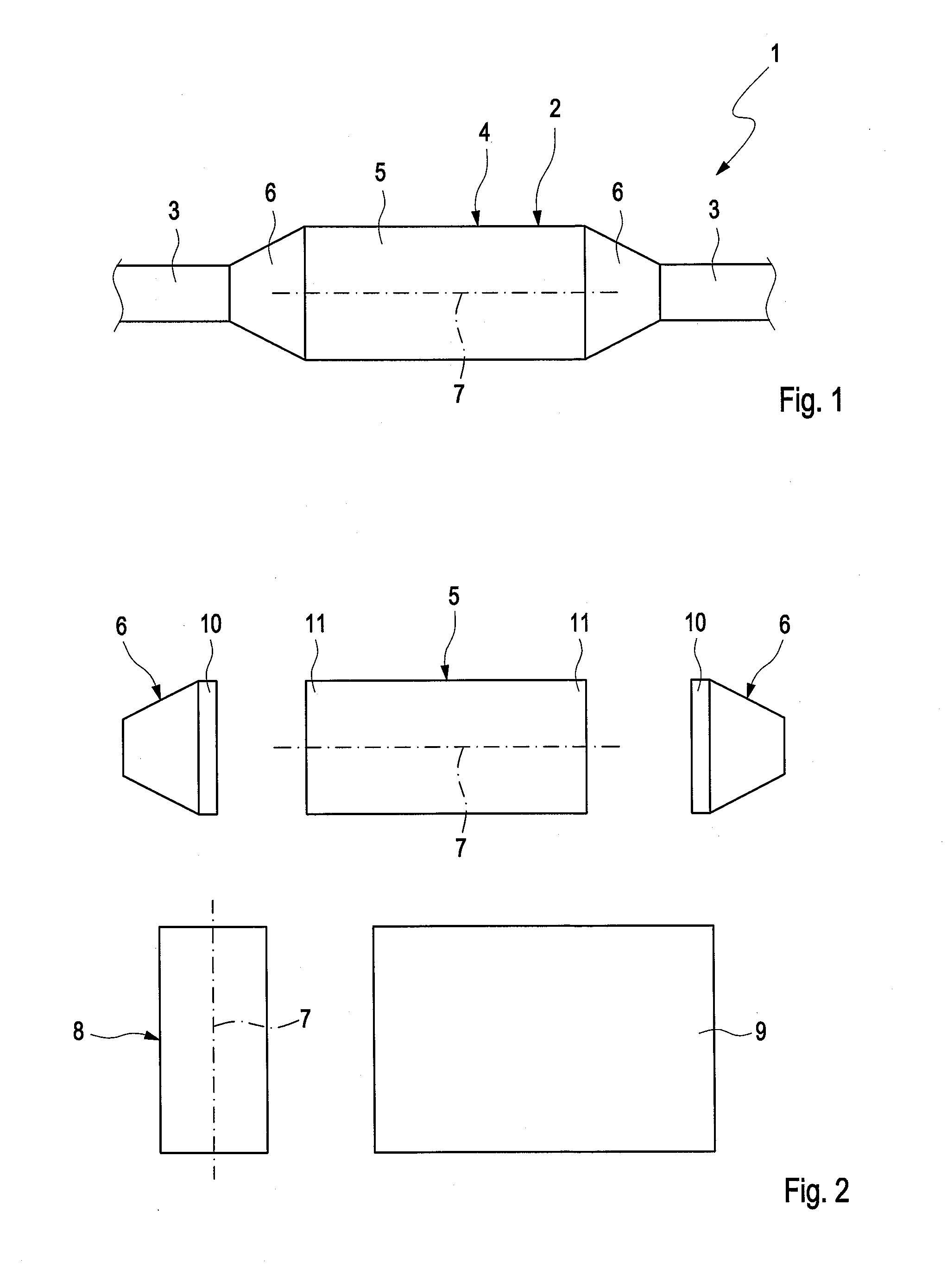
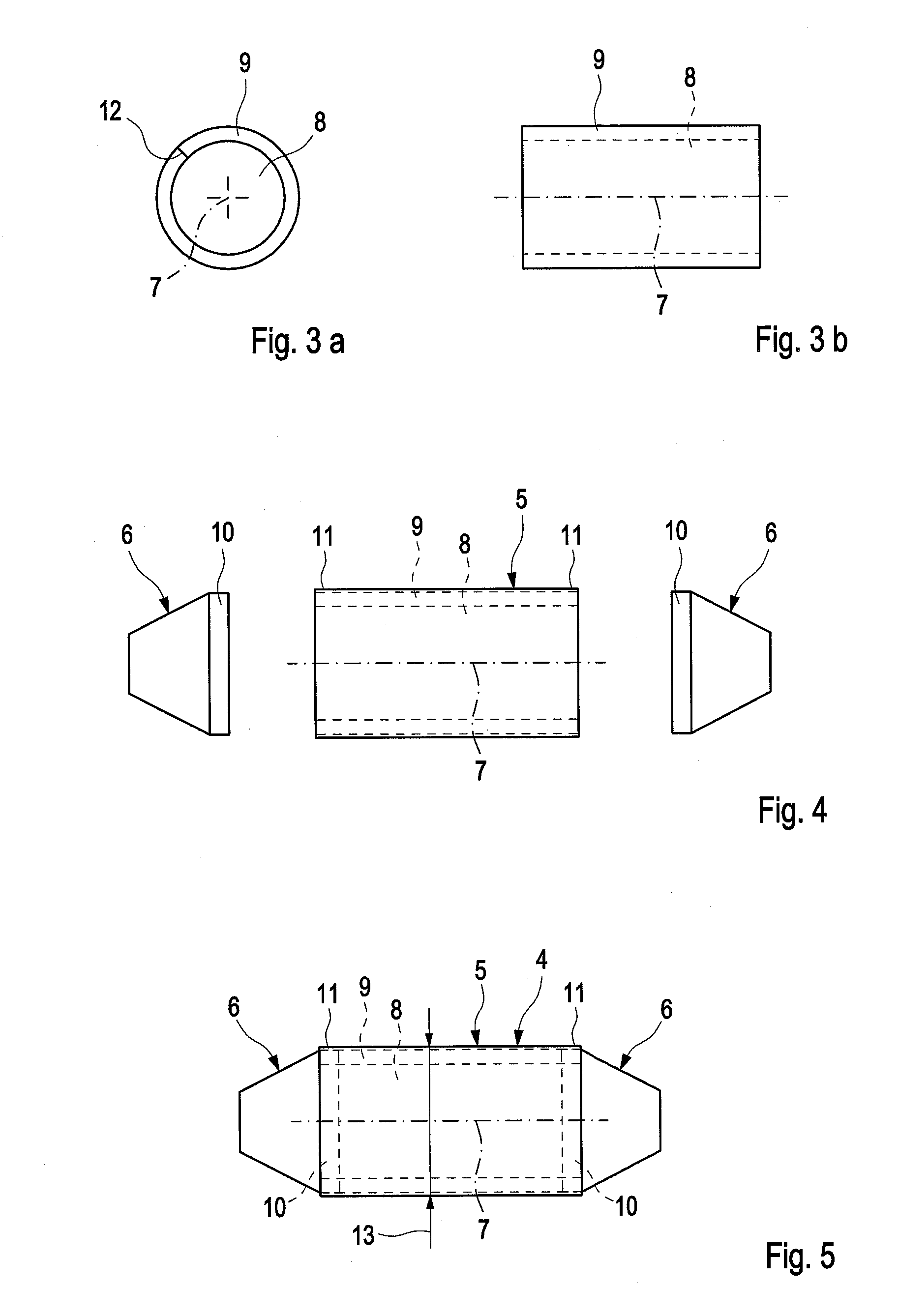
[0047]Referring to the drawings, according to FIG. 1, an exhaust system 1 for discharging exhaust gases of an internal combustion engine which is not shown here, which can be arranged in particular in a motor vehicle, comprises at least one exhaust gas aftertreatment device 2, which is incorporated in an exhaust line 3 of the exhaust system 1. The exhaust gas aftertreatment device 2 comprises a housing 4, which comprises a jacket 5 and two face-end funnels 6. The exhaust gas aftertreatment device 2 comprises a housing 4, which comprises a jacket 5 and two face-end funnels 6. Accordingly, the jacket 5 is closed in a circumferential direction, which relates to a longitudinal direction or axial direction 7 of the housing 4. In the half sections of FIGS. 6 to 10, the longitudinal axis 7 simultaneously represents a longitudinal center axis in which a symmetry plane is located.

[0048]As is evident from the FIGS. 2 to 4, the jacket 5 and the funnels 6 form separate components which have to ...


PUM

PropertyMeasurementUnit
Lengthaaaaaaaaaa
Thicknessaaaaaaaaaa
Forceaaaaaaaaaa

Abstract

A method for producing an exhaust-gas aftertreatment device (2) inserts a monolith (8) in a housing (4), assembled from a circumferentially enclosed jacket (5) and two end funnels. The monolith (8) is axially inserted into the jacket (5) with a circumferentially enclosing support mat (9). The funnels (6) are connected to the jacket (5) via an axial connecting section (10) shaped complementary to the cross-section of the jacket (5), such that each connecting section (10) and an axial end section (25) of the support mat (9) axially overlap. The jacket (5), including the connecting sections (10) of the funnels (6) from a starting cross-section (13) to an end cross-section (15). This produces a predetermined radial preload in the support mat (9) in a support area (16) extending from the one connecting section (10) to the other connecting section (10) to retain the monolith (8) in the jacket (5).

Description

CROSS REFERENCE TO RELATED APPLICATIONS[0001]This application is a United States National Phase Application of International Application PCT / EP2013 / 059783 filed May 13, 2013 and claims the benefit of priority under 35 U.S.C. §119 of German Patent Application 10 2012 208 449.5 filed May 21, 2012, the entire contents of which are incorporated herein by reference.FIELD OF THE INVENTION[0002]The present invention relates to a method for producing an exhaust gas aftertreatment device. The invention additionally relates to an exhaust gas aftertreatment device for an exhaust system of an internal combustion engine, which can be arranged in particular in a motor vehicle.BACKGROUND OF THE INVENTION[0003]Exhaust gas aftertreatment devices, such as for example catalytic converters and particles filters, can comprise at least one monolith for the exhaust gas aftertreatment, which is retained in a housing with the help of a bearing mat enclosing the monolith in the circumferential direction. Suc...

Claims


Application Information

Patent Timeline
IPC IPC(8): F01N13/18
CPCF01N13/1894F01N13/185F01N3/2853F01N2450/02F01N3/28F01N3/2867F01N2450/20F01N2450/22B23P15/00B23P2700/03Y10T29/49398
Inventor WIRTH, GEORGMULLER, BERND
Owner PUREM GMBH
Why Eureka
Try Eureka