Active exhaust pulse management

a technology of active exhaust and pulse management, which is applied in the direction of combustion engines, machines/engines, engine controllers, etc., can solve the problems of significant engine power and efficiency loss, high exhaust pressure pulsations in the split manifold, and high pressure in the exhaust valve. achieve the effect of improving turbocharged engine performance and exhaust pressur

Inactive Publication Date: 2015-05-07
FORD GLOBAL TECH LLC
View PDF4 Cites 21 Cited by
  • Summary
  • Abstract
  • Description
  • Claims
  • Application Information

AI Technical Summary

Benefits of technology

[0002]Split exhaust manifolds with pulse separation can be used to deliver higher exhaust pressure to the turbocharger resulting in improved turbocharged engine performance. Separated exhaust paths also prevent the trappi

Problems solved by technology

Even though split manifolds offer pulse preservation, depending on the engine speed they may expose exhaust valves to higher pressures under some conditions.
For example, even at lower speeds, exhaust pressure pulsations in the split manifold can be sufficiently high to force open the exhaust valves at untimely moments in the combustion cycle.
For example, exhaust pressure pulses can generate peak exhaust pressures in the split manifold that are sufficiently high to force open an exhaust valve during an intake stroke of the cylinder, inadvertently admitting exhaust gase

Method used


Image

  • Active exhaust pulse management
  • Active exhaust pulse management
  • Active exhaust pulse management

Examples


Embodiment Construction

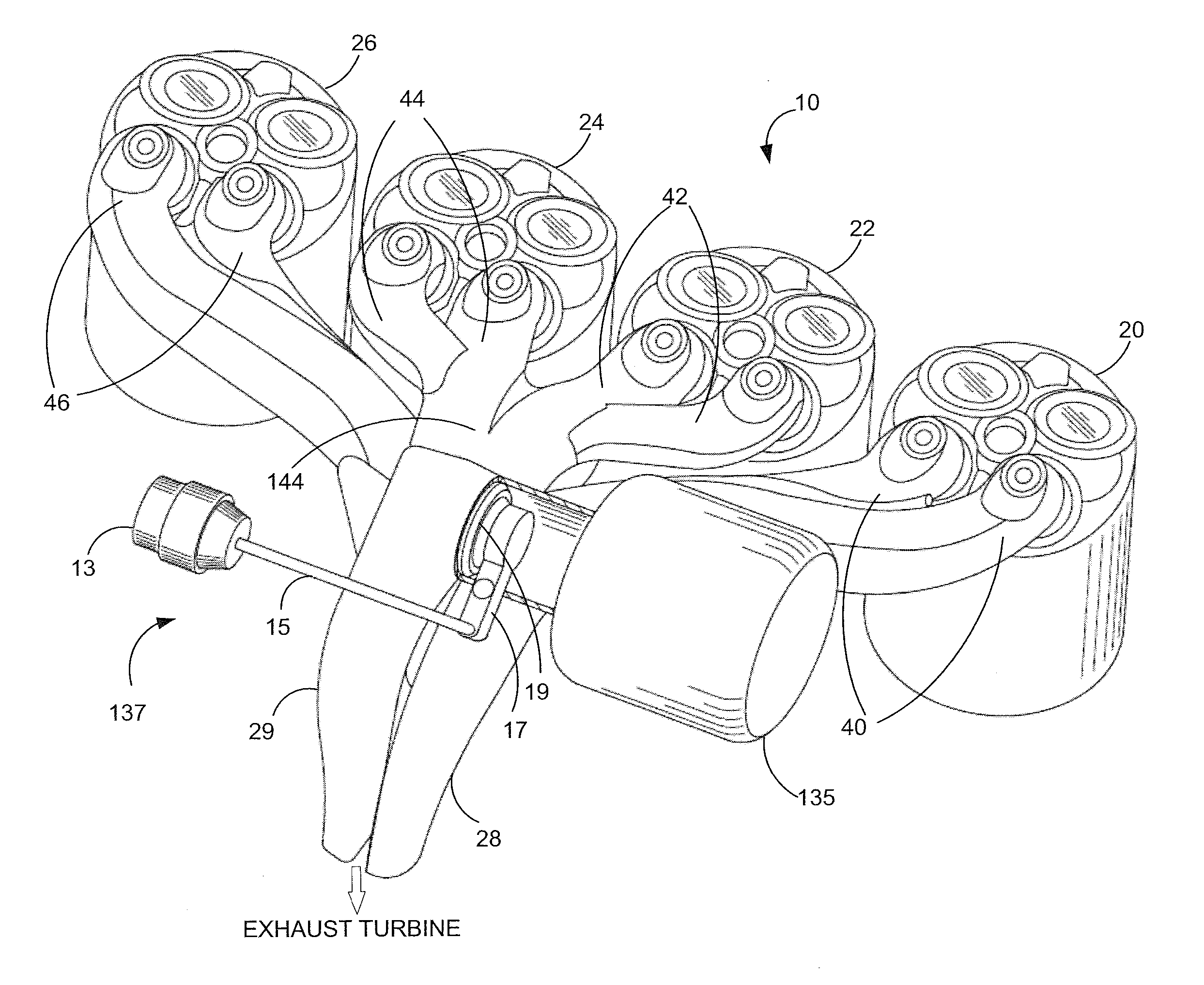
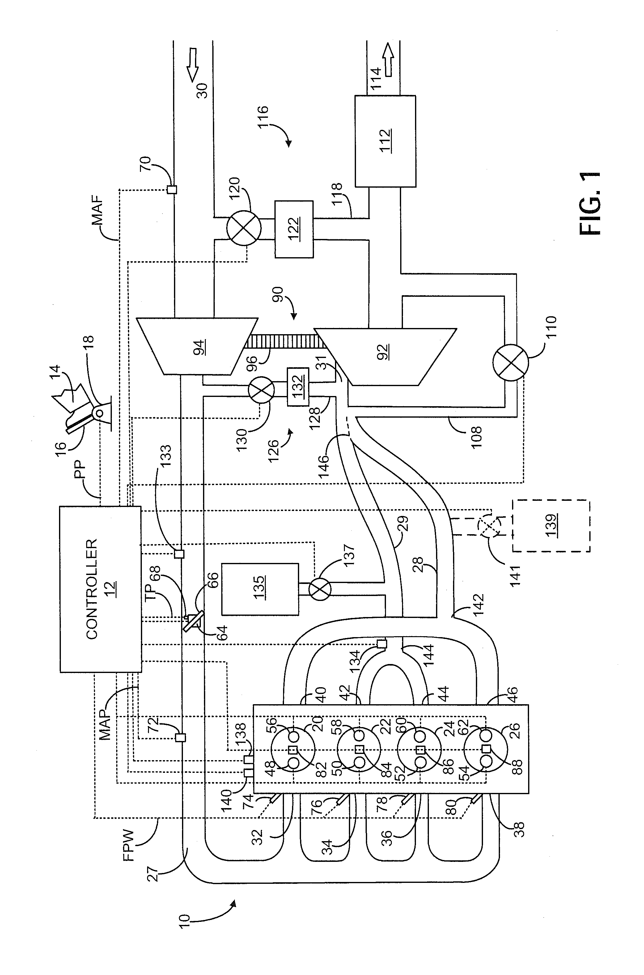
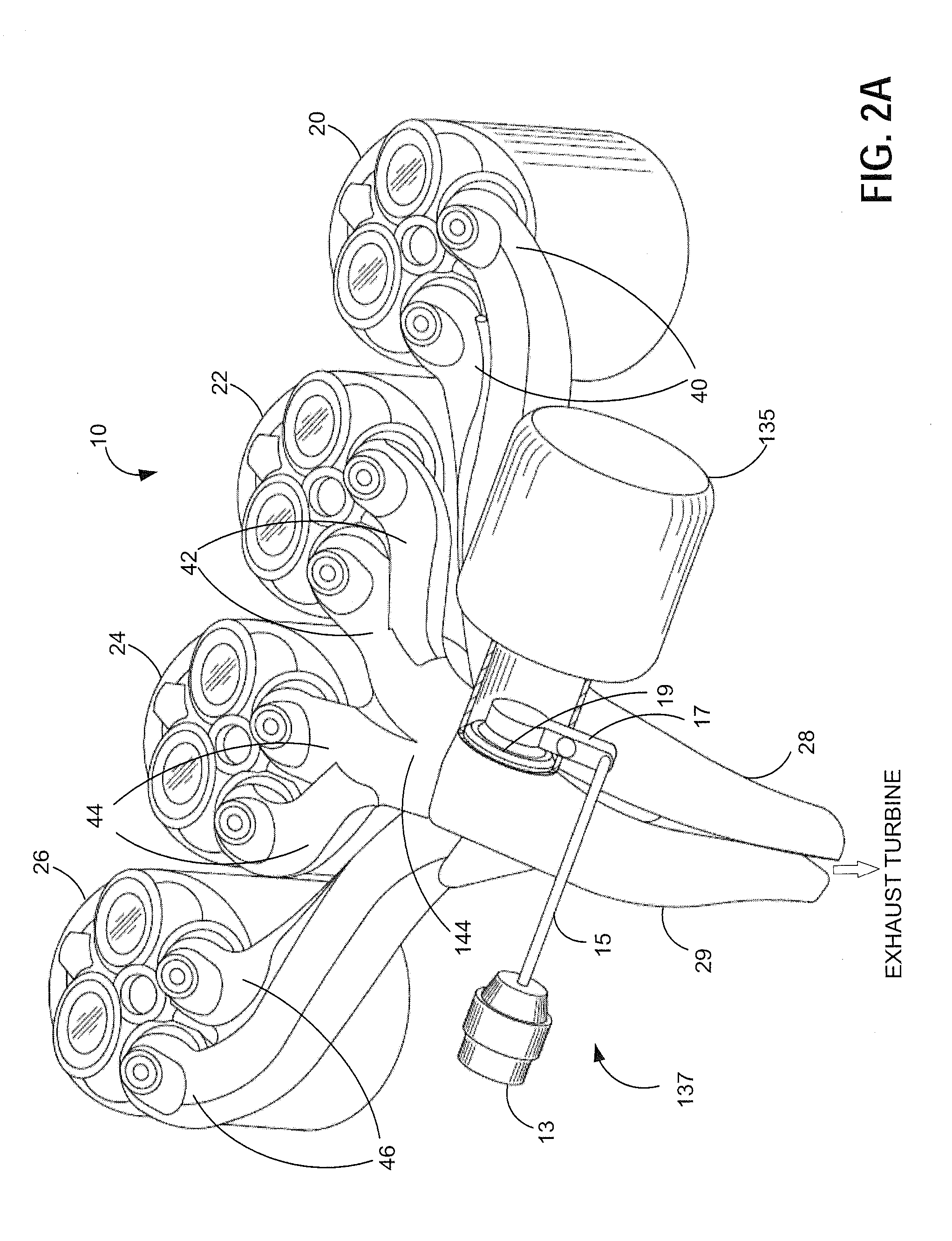
[0016]The following description relates to systems and methods for operating a boosted engine with a split exhaust manifold and an exhaust gas recirculation (EGR) system, as shown in FIG. 1. A controlled volume is attached to the exhaust pipe from cylinders 2 and 3 as shown in FIG. 2A. This volume can be opened or closed by a valve, as shown in FIGS. 2B and 2C, depending on the exhaust pressure in the manifold. A controller may be configured to perform a routine, such as the routine of FIG. 3, to adjust the position of this valve (such as from an initial position) based on various engine operating conditions. For example, the volume control valve position may be adjusted based on engine startup, tip-ins, presence of knocking or DFSO. The valve position may be adjusted during torque transients (FIG. 4), such as a tip-in, to reduce turbo lag. Torque disturbances associated with the opening or closing of the controlled volume may be compensated for using concomitant adjustments to one ...


PUM


Abstract

Methods and systems are provided for adjusting a volume control valve attached to a branch of a split exhaust manifold in a boosted engine system. Volume control valve adjustments are used at different engine operating conditions to improve engine performance and boost response. One example method includes closing the volume in response to a tip-in when increased boost is needed for exhaust turbine spool-up.

Description

FIELD[0001]The present application relates to a controlled volume with valve coupled to a split exhaust manifold in a boosted engine system.BACKGROUND AND SUMMARY[0002]Split exhaust manifolds with pulse separation can be used to deliver higher exhaust pressure to the turbocharger resulting in improved turbocharged engine performance. Separated exhaust paths also prevent the trapping of exhaust gases in adjacent cylinders which may cause misfiring of the cylinder. Diverse approaches may be used to control exhaust manifold pressure and turbine speed at varying operating conditions to regulate boost.[0003]One example approach is shown by Danet et al. in WO 2008 / 078020 wherein the boosted engine system includes a variable volume exhaust manifold. Therein, exhaust flow is directed via two separate paths to the twin scrolls of the turbocharger to provide boost and engine speed control. The split exhaust pipes are each connected to a storage volume upstream of the turbine and each volume i...

Claims


Application Information

Patent Timeline
IPC IPC(8): F02B37/22
CPCF02B37/22F02B37/02F02B37/025F02B37/12Y02T10/12
Inventor WADE, ROBERT ANDREWCURRIE, DAVID
Owner FORD GLOBAL TECH LLC
Why Eureka
Try Eureka