Exhaust denitrification device of engine

An engine and denitrification technology, applied in exhaust devices, engine components, engine control, etc., can solve the problems of large structure, exhaust temperature rise, reduced engine reliability and durability, etc.

Inactive Publication Date: 2002-09-11
KOMATSU LTD
View PDF1 Cites 7 Cited by
  • Summary
  • Abstract
  • Description
  • Claims
  • Application Information

AI Technical Summary

Problems solved by technology

[0004] But, in above-mentioned structure, owing to close EGR control valve when running normally, to make in the discharge gas contain a large amount of NOx, so must increase NOx absorber, cause the structural problem because of the large-scale engine because of floor area big, and it will increase the cost
In addition, if the amount of fuel is increased under high load, the pressure inside the barrel and the temperature of the exhaust gas will increase, reducing the reliability and durability of the engine

Method used


Image

  • Exhaust denitrification device of engine
  • Exhaust denitrification device of engine
  • Exhaust denitrification device of engine

Examples


Embodiment 1

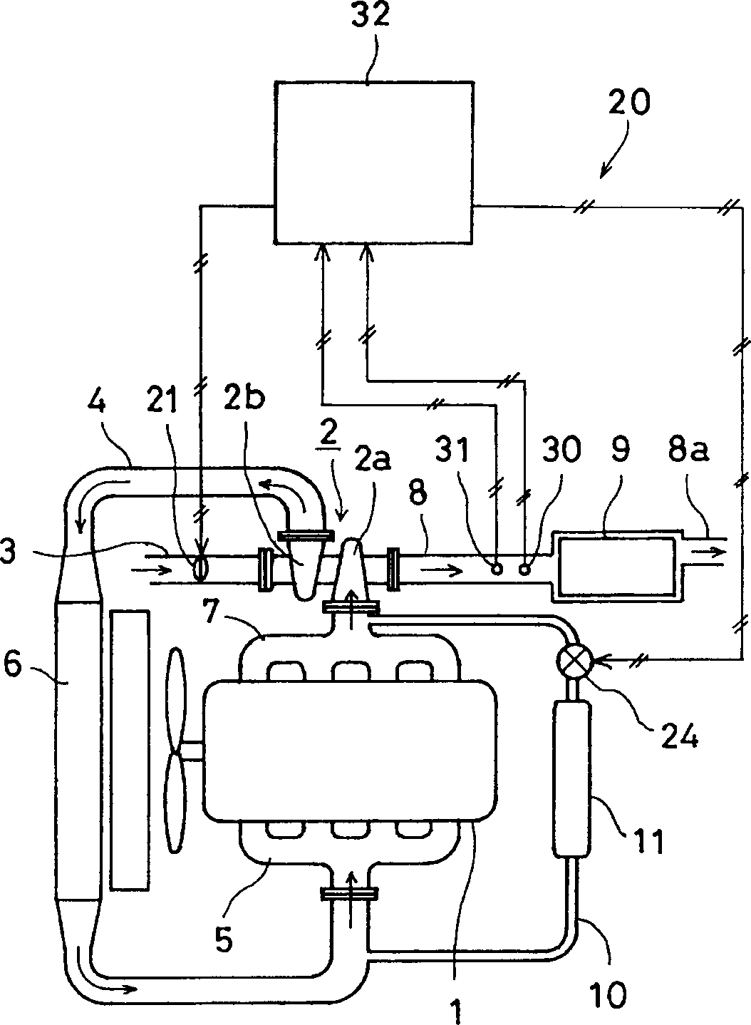
[0047] figure 1 It is a conceptual diagram of an engine exhaust gas denitrification device according to Embodiment 1 of the present invention. The engine 1 has a turbocharger 2 consisting of an exhaust turbine 2a and a compressor 2b. The exhaust turbine 2a is mounted on an exhaust manifold 7, and its outlet is provided with an exhaust pipe 8. A NOx absorbing catalyst 9 is installed in the exhaust pipe 8, and a tailpipe 8a is installed at the outlet thereof. A suction pipe 3 is installed at the suction port of the compressor 2b connected to the exhaust turbine 2a, and a suction throttle valve 21 with an adjustable opening area is arranged at the suction pipe 3. An air supply pipe 4 is attached to the discharge port of the compressor 2b, and a branch pipe 5 is connected to it, and an intercooler 6 is installed on the air supply pipe 4 .

[0048] The downstream of the intercooler 6 on the air supply pipe 4 and the upstream of the exhaust turbine 2 a in the exhaust branch pipe ...

Embodiment 2

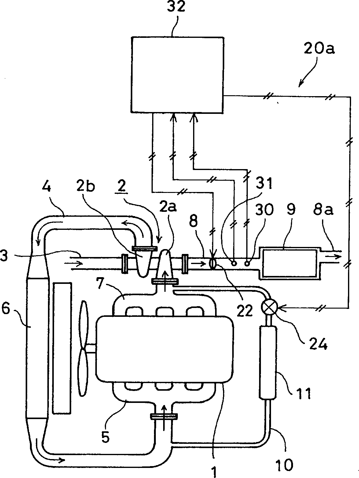
[0060] image 3 It is a conceptual diagram of the exhaust gas denitrification device of the second embodiment. Components that are the same as those in Embodiment 1 are denoted by the same symbols and their descriptions are omitted, and only the different parts will be described. exist image 3 In this embodiment, an exhaust throttle valve 22 is installed in the exhaust pipe 8 instead of the intake throttle valve 21, and is connected with the control device 32 to form an exhaust gas recirculation amount control mechanism 20a. When the air-fuel ratio of the exhaust gas is brought into a rich state, the control device 32 outputs a control signal to throttle the exhaust throttle valve 22 and open the EGR valve 24 . In this way, the pressure on the exhaust side rises and creates a large pressure difference with the supply air. Its action and effect are the same as those of Embodiment 1, so its description is omitted.

Embodiment 3

[0062] Figure 4 It is a conceptual diagram of the exhaust gas denitrification device of the third embodiment. Components that are the same as those in Embodiment 1 are denoted by the same symbols and their descriptions are omitted, and only the different parts will be described. exist Figure 4 In this embodiment, the suction throttle valve 21 is removed, and the air supply pipe 4 and the tail pipe 8a are connected with the air extraction pipe 12, and the air extraction valve 23 is provided in the air extraction pipe 12. The extraction valve 23 is connected with the control device 32 to form an exhaust gas recirculation amount control mechanism 20b. When the air-fuel ratio of the exhaust gas becomes rich, the control device 32 outputs a control signal to open the exhaust valve 23 to release a part of the supplied air to the outside. This reduces the supply air volume to make the exhaust gas rich, while keeping the supply air pressure to exhaust pressure ratio very small to...


PUM


Abstract

An exhaust gas denitrification device for an engine, which is provided with a NOx absorbing catalyst (9) for absorbing and releasing NOx, an exhaust gas recirculation flow path for mixing exhaust gas into inhaled gas, and an exhaust gas recirculation amount control mechanism ( 20, 20f); the exhaust gas recirculation amount control mechanism, when the stored amount of the absorbed NOx amount is below a specified value, recirculates the specified amount of reduced NOx with exhaust gas, and when the stored amount of the absorbed NOx amount When the amount exceeds a predetermined value and NOx is released, the exhaust gas exceeding the predetermined amount is recirculated to make the air-fuel ratio rich. The exhaust gas denitrification device of the engine can make the NOx absorbing catalyst miniaturized without reducing the reliability of the engine.

Description

technical field [0001] The invention relates to an exhaust denitrification device for an engine, in particular to an exhaust denitrification device for a diesel engine. Background technique [0002] So far, various proposals have been made for an exhaust gas denitrification device for a diesel engine, and the exhaust gas denitrification device for a diesel engine disclosed in JP-A-7-279718 is one example thereof. [0003] According to Japanese Patent Application Laid-Open No. 7-279718, a NOx absorbent is provided in an exhaust passage of an engine, and an exhaust gas recirculation (EGR) flow passage having an EGR control valve for controlling the amount of flowing exhaust gas is provided. The NOx absorbent absorbs NOx under normal conditions, releases NOx when the air-fuel ratio in the combustion chamber is rich, and reduces NOx with CO and CH. When the air-fuel ratio in the combustion chamber is rich, the EGR control valve is opened to recirculate the exhaust gas, the amou...

Claims


Application Information

Patent Timeline
Patent Type & Authority Applications(China)
IPC IPC(8): F01N3/08F02B37/00F02D21/08F02D41/00F02D41/02F02D41/14F02M25/07
CPCF01N3/0842F02B29/0425F02B37/00F02D21/08F02D41/0055F02D41/0275F02D41/146F02D41/1461F02D2200/0806F02M26/46F02M26/05F02M26/06F02M26/10F02M26/15F02M26/23F02M26/25F02M26/33F02M26/38Y02T10/40
Inventor 西山利彦若本晃太郎
Owner KOMATSU LTD
Why Eureka
Try Eureka