Heat pump heat exchanger having a low pressure drop distribution tube

a heat exchanger and distribution tube technology, which is applied in the direction of heat exchanger casings, heat exchange apparatus, light and heating apparatus, etc., can solve the problems of poor refrigerant distribution uneven temperature distribution over the core, and mal-distribution of refrigerant through the refrigerant tubes, so as to reduce the pressure drop of the outlet manifold and improve the evaporator performan

Inactive Publication Date: 2015-05-07
MAHLE INT GMBH
View PDF11 Cites 15 Cited by
  • Summary
  • Abstract
  • Description
  • Claims
  • Application Information

AI Technical Summary

Benefits of technology

[0014]The improved distribution tube design provides similar refrigerant distribution as that of the full length distribution tube when functioning as an outlet collector, but improves evaporator performance by as much as 15% by reducing the outlet manifold pressure drop. The improved distribution tube has minimal, if any adverse effect when the heat pump heat exchanger operates in condenser mode, in which the improved distribution tube functions as an inlet distributor.

Problems solved by technology

For a heat pump heat exchanger operating in evaporator mode, the increased length of the manifolds tends to result in refrigerant mal-distribution through the refrigerant tubes.
The effects of momentum and gravity, due to the large mass differences between the liquid and gas phases, can result in separation of the phases in the inlet manifold and cause poor refrigerant distribution through the refrigerant tubes.
Poor refrigerant distribution degrades evaporator performance and can result in uneven temperature distribution over the core.
Outlet pressure drop in the outlet collector reduces performance by both constraining refrigerant flow, inducing refrigerant flow mal-distribution, and raising the core inlet pressure and temperature.

Method used


Image

  • Heat pump heat exchanger having a low pressure drop distribution tube
  • Heat pump heat exchanger having a low pressure drop distribution tube

Examples


Embodiment Construction

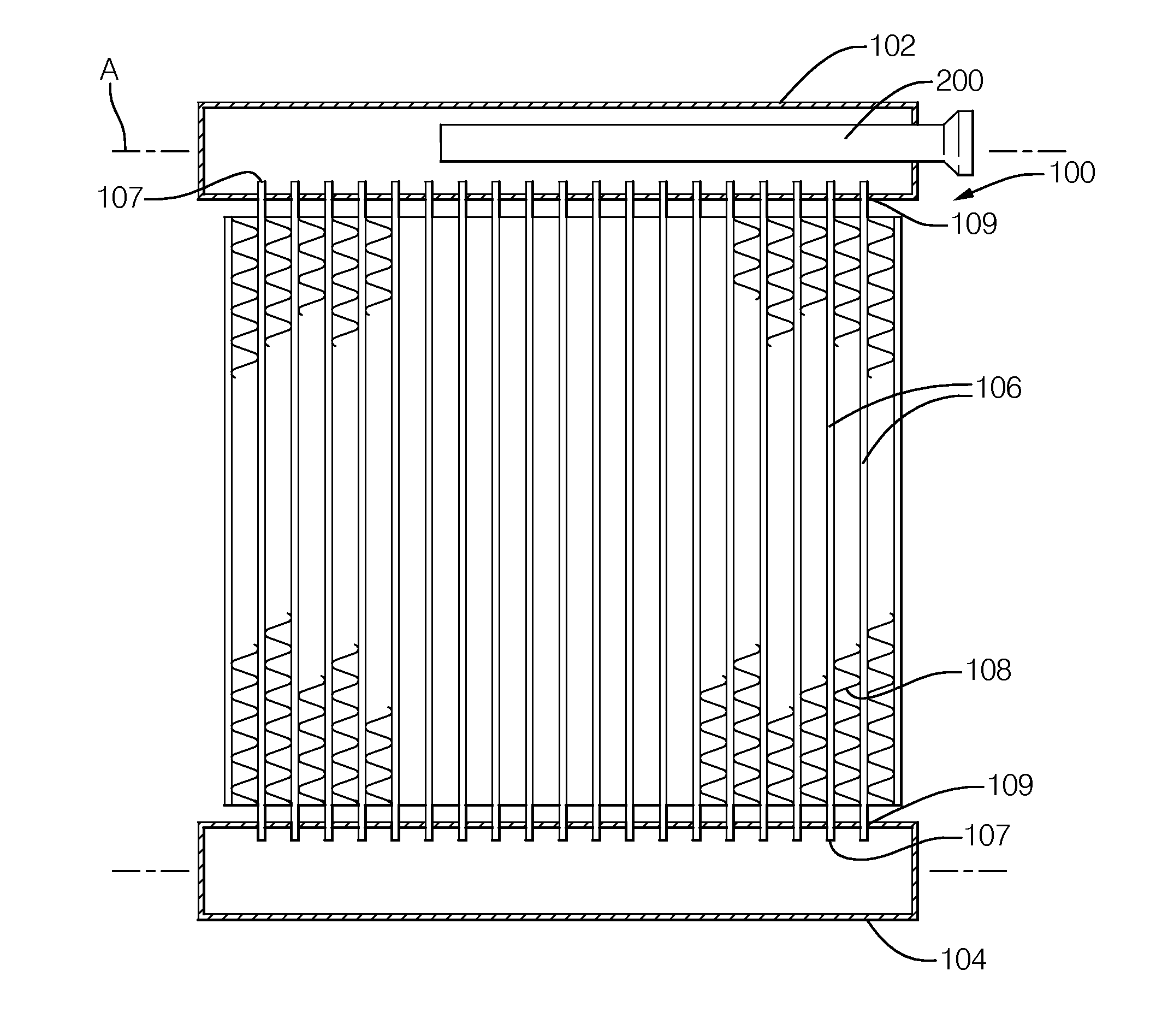
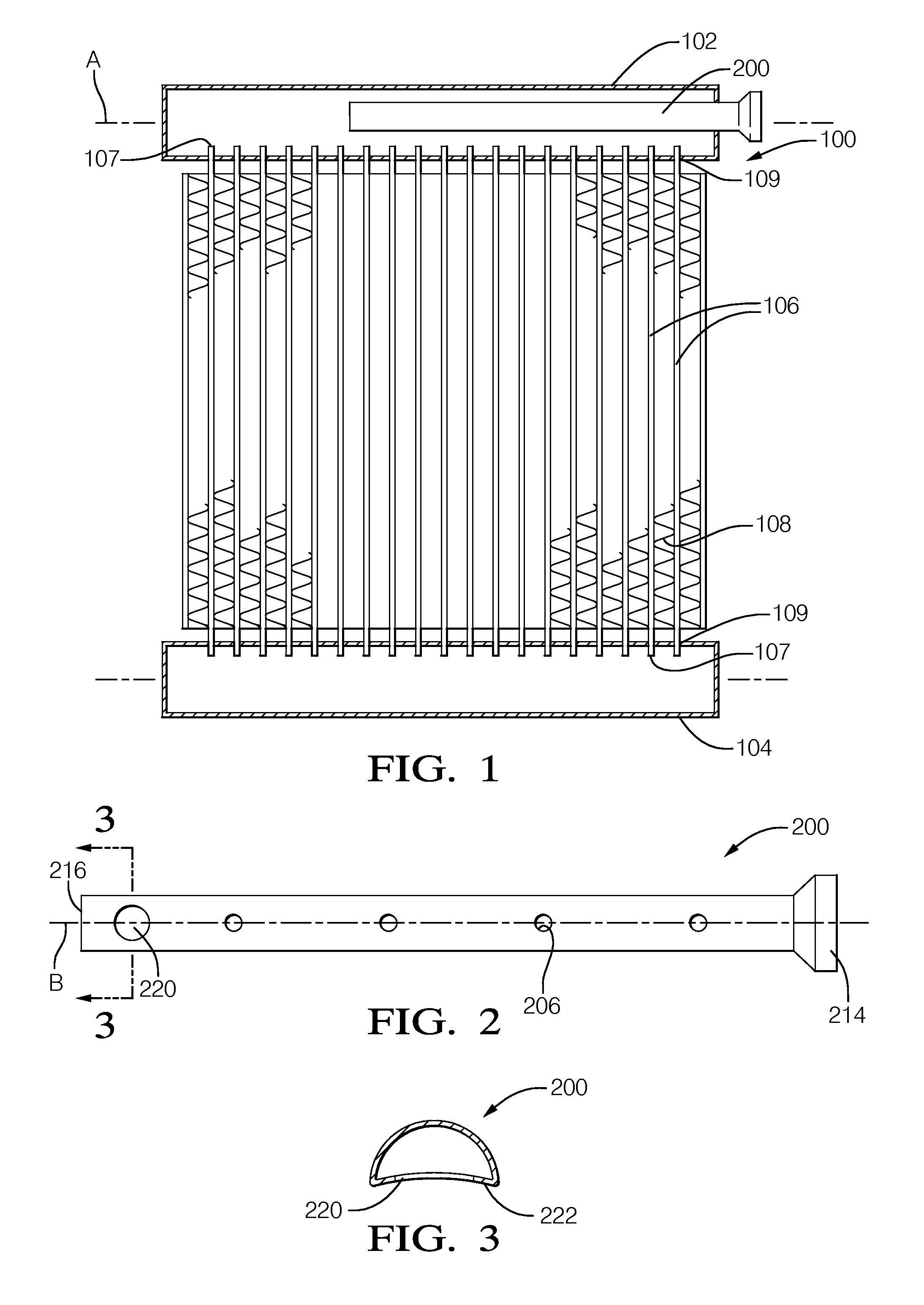
[0020]Shown in FIG. 1 is the exemplary heat pump heat exchanger 100 of the current invention configured to operate as an evaporator and as a condenser depending on whether the heat pump system is in cooling or heating mode. Heat pump heat exchangers are also known as heat pump coils in the art. The heat exchanger assembly 100 includes a first manifold 102, a second manifold 104, and plurality of refrigerant tubes 106 hydraulically connecting the manifolds 102, 104. The refrigerant tubes 106 include opposite open ends 107 that are inserted through corresponding tube slots 109 positioned along the manifolds 102, 104 for refrigerant flow between the manifolds 102, 104. A plurality of fins 108 is disposed between adjacent refrigerant tubes 106 to facilitate heat exchange between the refrigerant flowing within the refrigerant tubes 106 and a stream of ambient air flowing pass the refrigerant tubes 106 and fins 108. The manifolds 102, 104, refrigerant tubes 106, and fins 108 are formed of...


PUM


Abstract

A heat pump heat exchanger includes a first manifold, a second manifold spaced from the first manifold, a plurality of refrigerant tubes hydraulically connecting the manifolds, and a distribution tube disposed in the first manifold. The distribution tube includes an inlet end, a distal end opposite the inlet end, a plurality of orifices between the inlet end and the distal end. The distribution tube also includes a terminal aperture immediately adjacent the distal end, wherein the terminal aperture includes an open aperture area greater than any one of the open orifice area. The open aperture area is large enough to provide a uniform refrigerant collection with acceptable minimal pressure drop in evaporative mode, but small enough to prevent vapor overflow to an area of the manifold adjacent to the distal end in condenser mode. The length of the distribution tube is less than 3/4 the length of the first manifold.

Description

CROSS-REFERENCE TO RELATED APPLICATION[0001]This application claims the benefit of U.S. Provisional Patent Application Ser. No. 61 / 727,173 for a HEAT EXCHANGER HAVING A LOW PRESSURE DROP OUTLET COLLECTOR, filed on Nov. 16, 2012, which is hereby incorporated by reference in its entirety.TECHNICAL FIELD OF INVENTION[0002]The present disclosure relates a heat pump heat exchanger; more particularly, to a heat pump heat exchanger having a distribution tube.BACKGROUND OF INVENTION[0003]Residential and commercial air conditioning and heat pump systems are known to employ modified automotive heat exchangers, which are desirable for its proven high heat transfer efficiency, durability, and relatively ease of manufacturability, as heat pump heat exchangers. A conventional automotive heat exchanger typically includes an inlet manifold, an outlet manifold, and a plurality of refrigerant tubes hydraulically connecting the manifolds for refrigerant flow therebetween. Corrugated fins interconnect ...

Claims


Application Information

Patent Timeline
Patent Type & Authority Applications(United States)
IPC IPC(8): F28F9/02
CPCF28F9/0273
Inventor XIA, YANPINGJOHNSON, RUSSELL S.
Owner MAHLE INT GMBH
Why Eureka
Try Eureka