Temperature-controlled window and mehtod of controlling thereof

a technology of temperature control and mehtod, which is applied in the direction of door/window protective devices, process and machine control, instruments, etc., can solve the problems of temperature variation, lcd layer activation too early or too late, and temperature measurement outside and not inside the room, etc., and achieve the effect of less cos

Active Publication Date: 2015-05-07
WICURIT APS
View PDF38 Cites 87 Cited by
  • Summary
  • Abstract
  • Description
  • Claims
  • Application Information

AI Technical Summary

Benefits of technology

[0025]The object of the present invention is to provide a window that intends to solve the problems of the prior art in a more simple and thereby less costly way.

Problems solved by technology

The system has the disadvantage that the temperature is measured outside and not inside the room whereby the temperature sensor is heated more quickly than the room.
Thus there is a risk that the LCD layer is activated too early or too late in relation to the desired temperature in the room.
The system has the disadvantage that the temperature sensor measures a point in the room, typically close to the floor or at a wall, implying that the temperature may vary at other points in the room if the case is a relatively large or long room.
If the temperature sensor is not disposed at an optimal location in the room the system will furthermore not perform a correct regulation of the temperature in the room.
This manual programming of the radiator thermostats is both tedious and time-consuming.

Method used


Image

  • Temperature-controlled window and mehtod of controlling thereof
  • Temperature-controlled window and mehtod of controlling thereof
  • Temperature-controlled window and mehtod of controlling thereof

Examples


first embodiment

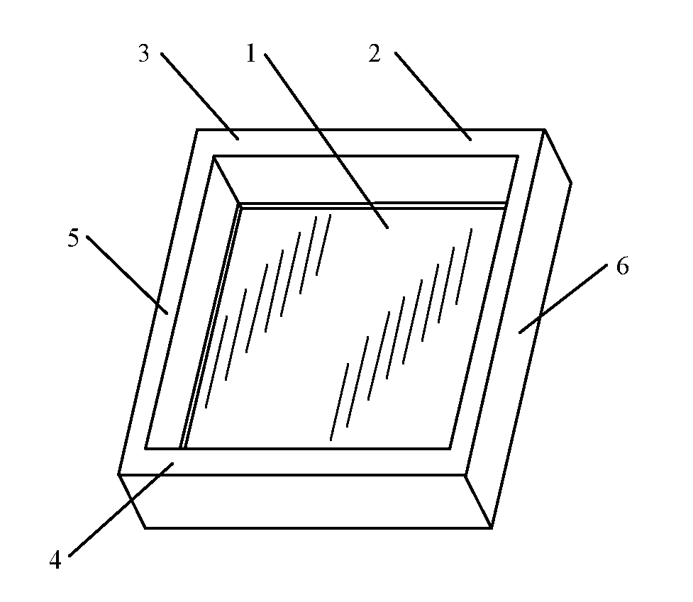
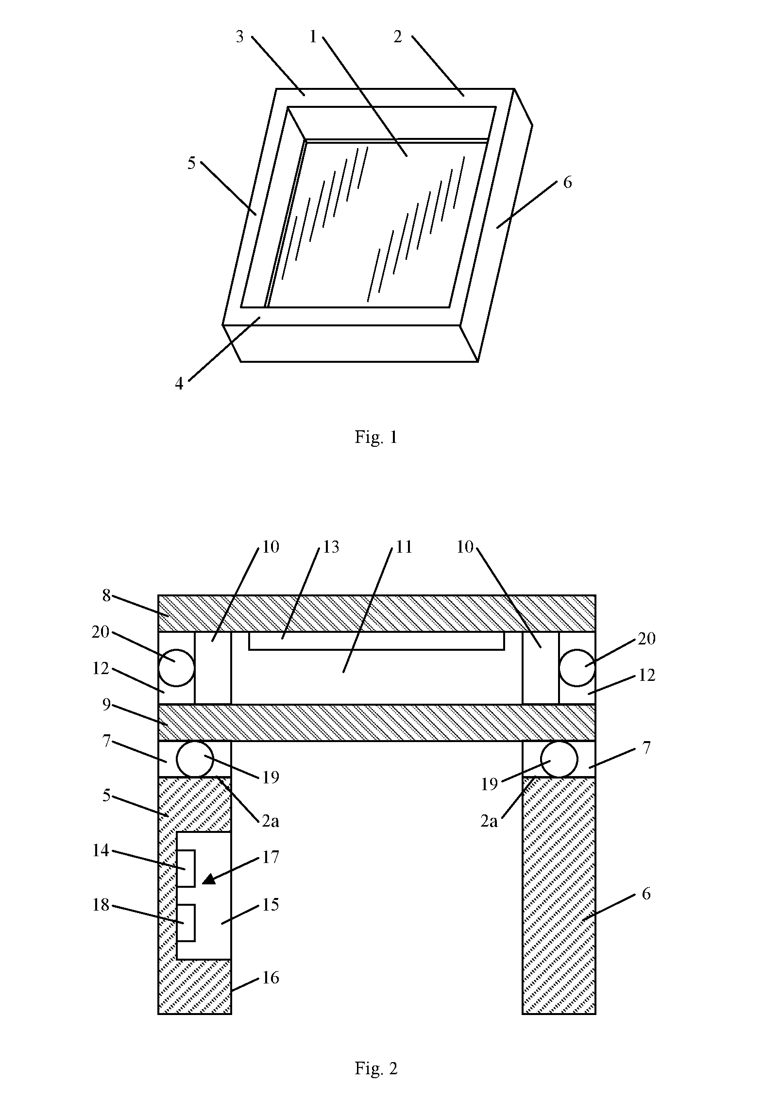
[0073]FIG. 2 shows a cross-section of a first embodiment according to the invention wherein the window pane 1 is connected to an end face 2a on the window frame 2 via a joint 7. The joint 7 can be a glue joint, a rubber joint or other suitable joint configured to retain the window pane 1 in the window frame 2. In this embodiment, the window frame 2 is designed as a narrow window frame. The window pane 1 can include two, three or more glass panes 8, 9 separated by a number of spacers 10 such that the glass panes 8, 9 and the spacers 10 together form a cavity 11. The cavity 11 along the edge of the glass panes 8, 9 can be sealed by means of silicone, elastic joint filler or other suitable sealing material 12. The cavity 11 can be filled with a gas such as krypton, argon, air or other suitable gas.

[0074]A layer of light-transmitting material 13 such as electrochrome, fluid crystals (called LCD), thermochrome, window film, sunfilm, UV-film, or other suitable material can be provided at ...

second embodiment

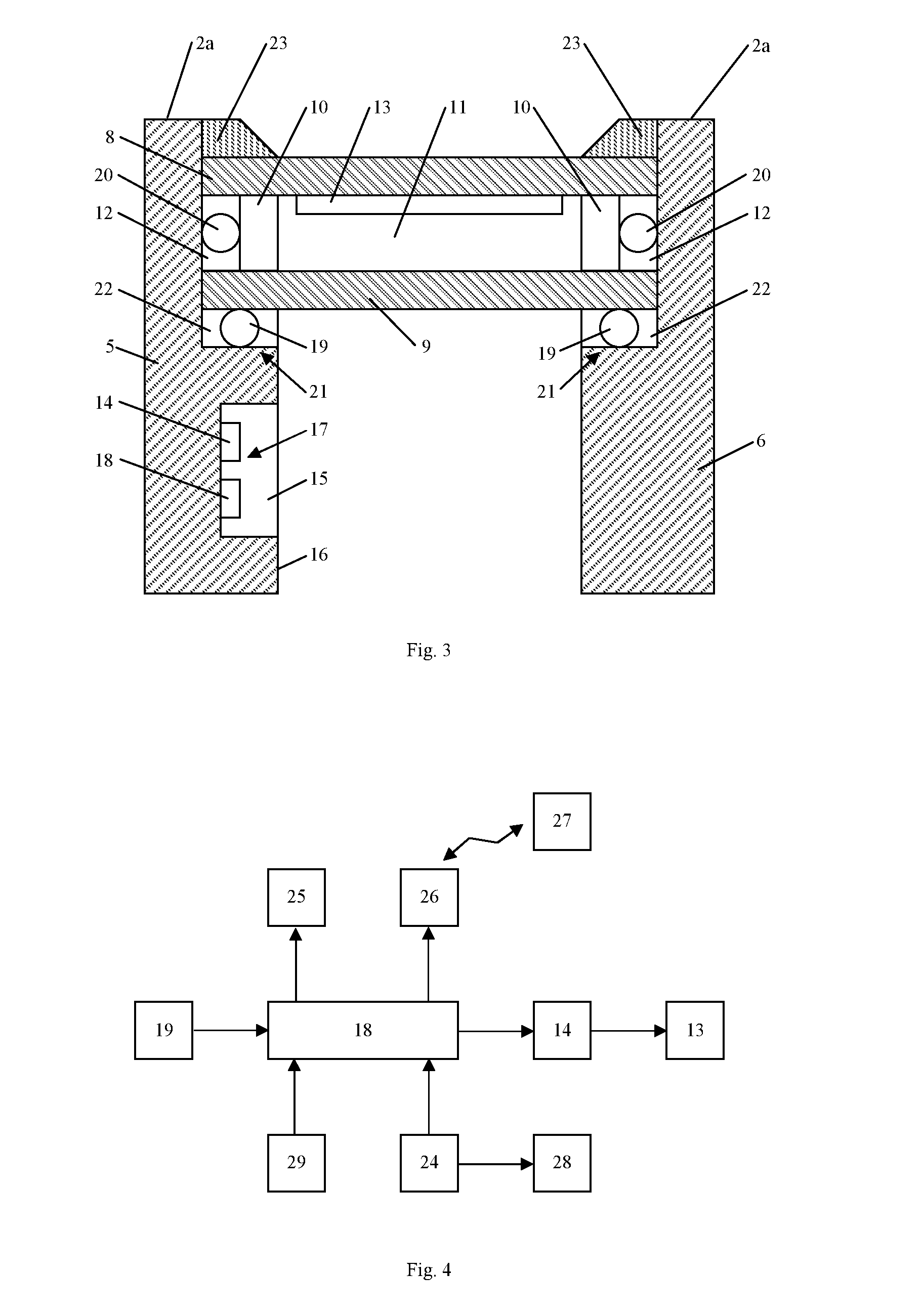
[0079]FIG. 3 is a cross-section of a second embodiment according to the invention which differs from the cross-section in FIG. 2 in that the pane 1 is disposed in cutout 21 in the form of rabbet on the window frame 2. In this embodiment, the window frame 2 is designed as a wide window frame in which the rabbet can be formed along the inner side face 16 and the end face 2a of the window frame 2.

[0080]In this embodiment, the window pane 1 can be provided on a number of spacer blocks (not shown) in the bottom member 4, wherein along the periphery of the inner side 9a of the window pane 1 there may be provided a second joint 22 in the form of a rubber band, an elastic joint filler or other suitable joint. The window pane 1 can be retained in the rabbet 21 by means of an edge profile 23 which can be disposed at the outer side 8b of the window pane 1 and can include a joint (not shown) facing the joint 22.

[0081]FIG. 4 shows a simplified layout of the electric circuit 16 according to an em...

third embodiment

[0096]In a third embodiment, control of the window 30 can be performed by means of an application configured to run on the communication unit 32. The application can be configured to communicate with the server 31 via a wireless communication module in the communication unit 32. The application can be configured to communicate with the window 30 by means of the wireless communication module 26 in the window 30. The application can be designed to control the functions in the window 30 by means of one or more graphic user interfaces. One or more of the graphic user interfaces can be designed to visually indicate (via text or graphics) one or more of the measurements performed in the window 30, e.g. the temperatures Tm, Tr, air pressure, light index or other measurement. The user can control the functions in the window 30 by means of the application and possibly perform a change in one or more of the parameters by which the window 30 is controlled. The operating panel 25 can hereby be ...


PUM


Abstract

The invention concerns a window including a window pane with one or more glass panes, a window frame in which the window pane is provided, at least one temperature sensor arranged in or at the periphery of the window pane, and an electric circuit connected to the temperature sensor mounted on or in the window frame. The electric circuit is configured to be connected to an operation unit which is configured to regulate the incident light through the window pane. The invention furthermore concerns a method for controlling a window wherein the electric circuit controls the means configured to regulate the incident light through the window pane based on a set of parameters. The parameters are determined on the basis of the orientation and geographical position of the window whereby the supply of free energy is optimised and the amount of energy supplied from energy sources in the room is reduced. In an embodiment the window can be controlled by means of an application configured to run on a mobile communication unit.

Description

BACKGROUND OF THE INVENTION[0001]1. Field of the Invention[0002]The present invention concerns a method for regulating the indoor climate in[0003]at least one room in a building, comprising:[0004]at least one first unit configured to supply energy from an energy source to the room;[0005]at least one second unit connected to the first unit and controlling the energy supply from the first unit based on at least one measured temperature, where control of the energy supply from the first unit is performed on the basis of on one or more sets of parameters;[0006]at least one third central unit configured to communicate with the second unit, wherein the method includes the following steps[0007]the third unit generates the set of parameters based on one or more sets of data describing the external, ambient conditions that influence the indoor climate, for example meteorological data for a geographical area in which the first unit is located.[0008]2. Description of Related Art[0009]The prese...

Claims


Application Information

Patent Timeline
Patent Type & Authority Applications(United States)
IPC IPC(8): E06B9/24H05B1/02E06B7/28E06B3/67E06B5/00
CPCE06B9/24E06B3/67E06B2009/2464E06B7/28H05B1/0275E06B5/00G05D23/1917
Inventor PETERSEN, LARS
Owner WICURIT APS
Why Eureka
Try Eureka