Motor driving circuit

a technology of stepping motor and driving circuit, which is applied in the direction of electronic commutation motor control, control system, dynamo-electric converter control, etc., can solve the problems of increasing the cost of an increased number of components, the stepping motor goes out of synchronization, and the disadvantage of large power loss, so as to reduce the circuit area and uniform characteristics

Active Publication Date: 2015-05-07
ROHM CO LTD
View PDF1 Cites 18 Cited by
  • Summary
  • Abstract
  • Description
  • Claims
  • Application Information

AI Technical Summary

Benefits of technology

[0023]Examples of such a “monolithically integrated” arrangement include: an arrangement in which all the circuit components are formed on a semiconductor substrate; and an arrangement in which principal circuit components are monolithically integrated. Also, a part of the circuit components such as resistors and cap...

Problems solved by technology

However, when a sudden change in the load or a sudden change in speed occurs, the stepping motor goes out of synchronization.
However, such an arrangement has a disadva...

Method used


Image

  • Motor driving circuit
  • Motor driving circuit
  • Motor driving circuit

Examples


modification 1

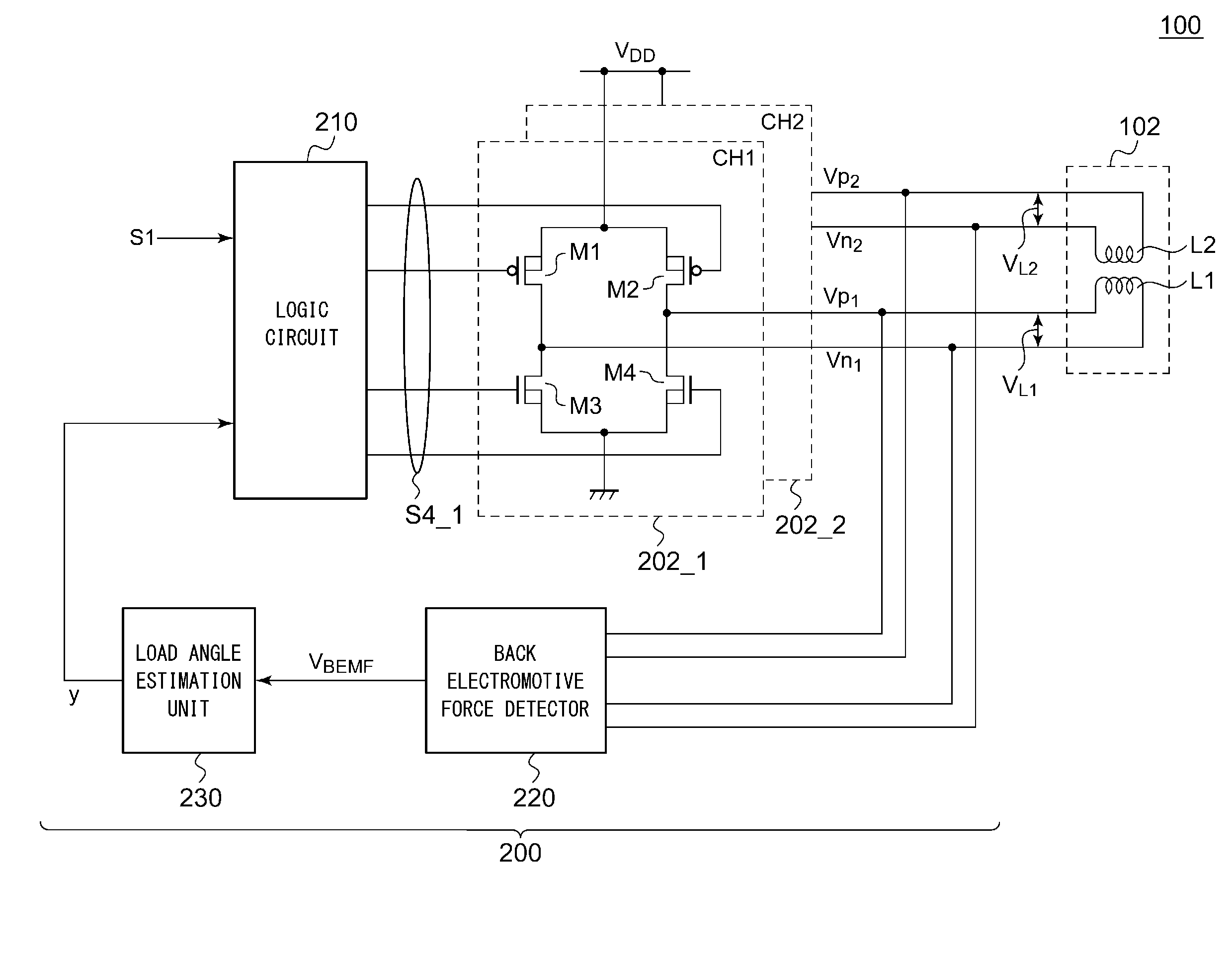
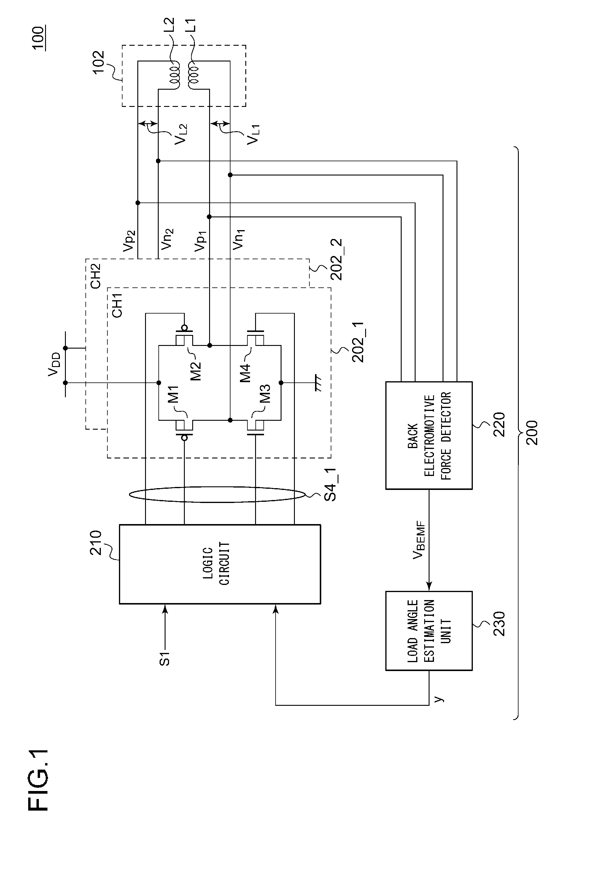
[0116]The logic circuit 210 may adjust the power supply voltage VDD supplied to the bridge circuit 202 instead of or otherwise in combination with the adjustment of the duty ratio of the control pulse S2 such that the load angle φ approaches the target angle φREF. By changing the power supply voltage VDD, such an arrangement is capable of changing the electric power supplied to the coils L1 and L2 of the stepping motor 102.

second modification

[0117]The logic circuit 210 is capable of detecting whether or not step-out has occurred, and / or detecting a sign of step-out, based on the load angle φ estimated by the load angle estimation unit 230. For example, the logic circuit 210 may detect a situation in which the estimated load angle φ exceeds 90 degrees or otherwise a situation in which the estimated load angle φ approaches 90 degrees. Also, the logic circuit 210 may output, to an external processor (not shown), a notice signal which indicates the presence or absence of step-out, and / or a sign of step-out, thereby notifying an external circuit of the presence or absence of step-out, and / or a sign of step-out. This allows such an external processor to start a sequence for returning from the step-out state to the normal state.

modification 3

[0118]Description has been made in the embodiment regarding an arrangement in which the output stage of the bridge circuit 10 is configured as a full-bridge circuit. However, the present invention is not restricted to such an arrangement. Also, the output stage may be configured as a half-bridge circuit.


PUM


Abstract

A logic circuit controls a bridge circuit connected to a coil of a stepping motor in synchronization with an input pulse, so as to control electric power supplied to the coil of the stepping motor. A back electromotive force detector detects the back electromotive force VBEMF across the coil L. A load angle estimation unit estimates the load angle φ based on the back electromotive force detected in the detection period set in the high-impedance period set for the coil L. A logic circuit is configured to adjust electric power supplied to the coil such that the estimated load angle φ approaches a predetermined target angle φREF.

Description

CROSS REFERENCE[0001]The present invention claims priority under 35 U.S.C. §119 to Japanese Application No. 2013-231481 filed Nov. 7, 2013, the entire content of which is incorporated herein by reference.BACKGROUND OF THE INVENTION[0002]1. Field of the Invention[0003]The present invention relates to a driving technique for a stepping motor.[0004]2. Description of the Related Art[0005]In many cases, various kinds of electronic devices such as digital still cameras, digital video cameras, disk apparatuses, printers, copiers, and the like employ stepping motors for various kinds of operations such as adjustment of the position of movable components such as lenses, pickup heads, print heads, etc., driving operations for driving a sheet feeder roller, and the like. Such a stepping motor is configured as a synchronous motor that rotates in synchronization with an input pulse applied by an external circuit. The stepping motor has high controllability for starting, stopping, and positioning...

Claims


Application Information

Patent Timeline
IPC IPC(8): H02P8/12
CPCH02P8/12H02P6/182H02P2203/09
Inventor INOUE, SHIGEYUKI
Owner ROHM CO LTD
Why Eureka
Try Eureka