
Mobile device and antenna structure with conductive frame

a mobile device and antenna structure technology, applied in the field of mobile devices, can solve problems such as reducing the communication quality of mobile devices

Inactive Publication Date: 2015-05-07
ACER INC
View PDF5 Cites 77 Cited by
  • Summary
  • Abstract
  • Description
  • Claims
  • Application Information

AI Technical Summary

Benefits of technology

The invention is a mobile device that solves problems related to signal interference. It includes a ground element, a signal source, and three separate conductive frames. The three frames form an antenna structure that helps reduce interference and improves signal quality. The device also has a feeding element, a first radiation element, a second radiation element, and a second conductive frame. The second radiation element is positioned between the second and third conductive frames. The technical effect of this invention is to provide a mobile device with improved signal quality and reduced interference.

Problems solved by technology

However, these exterior metal elements often negatively affect the antenna structure in the mobile device for wireless communication, thereby reducing the communication quality of the mobile device.

Method used


Image

  • Mobile device and antenna structure with conductive frame
  • Mobile device and antenna structure with conductive frame
  • Mobile device and antenna structure with conductive frame

Examples


Embodiment Construction

[0015]In order to illustrate the purposes, features and advantages of the invention, the embodiments and figures thereof in the invention are shown in detail as follows.

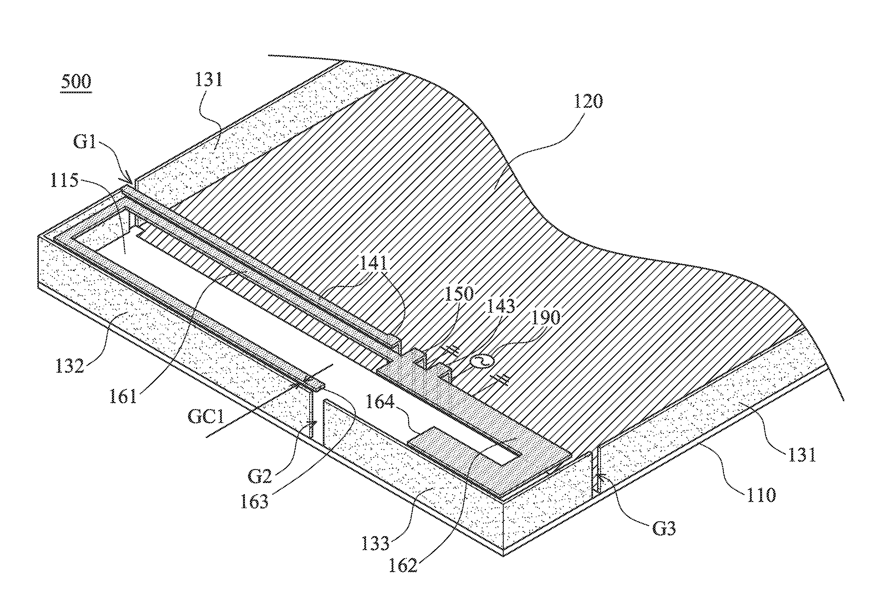
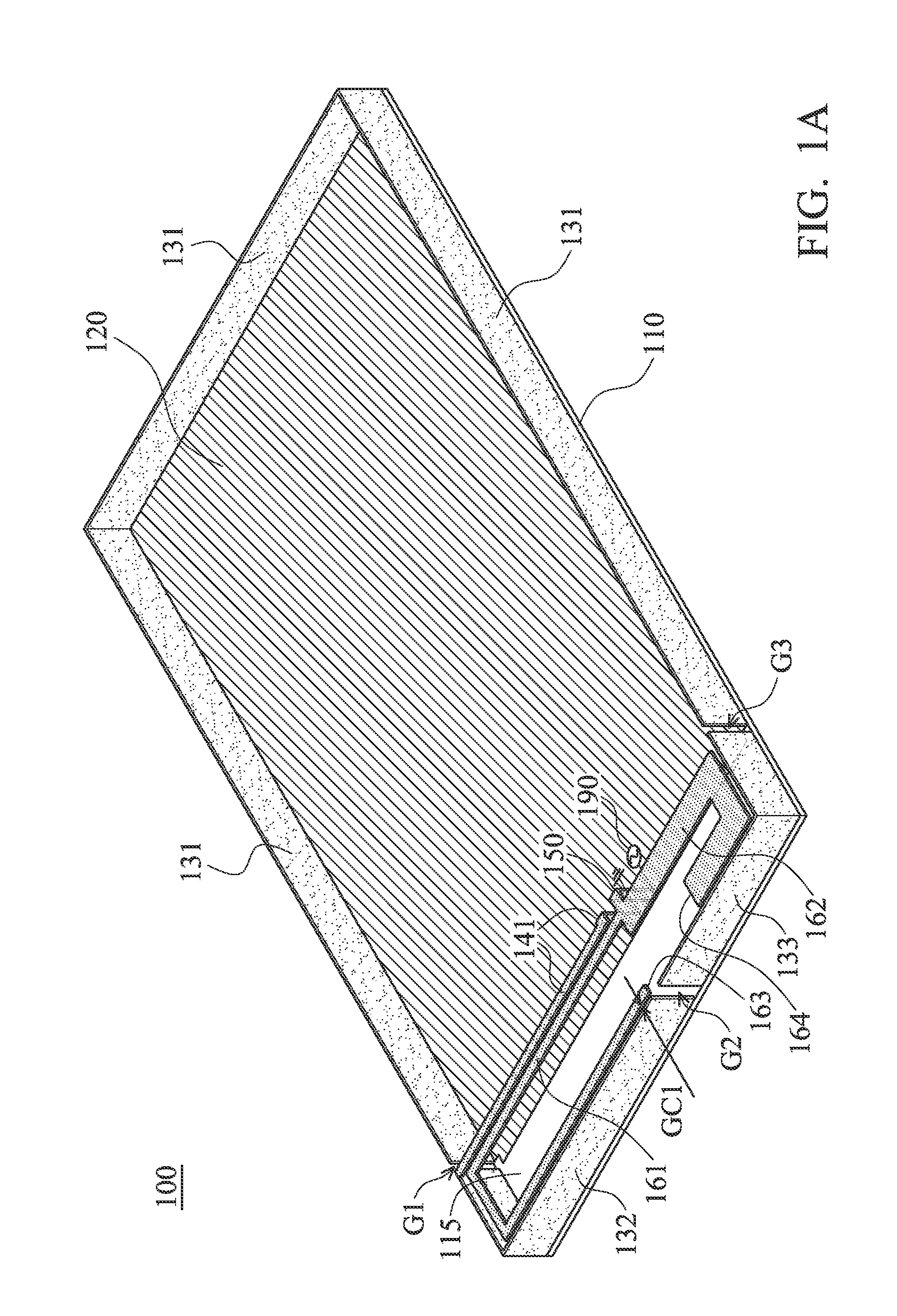
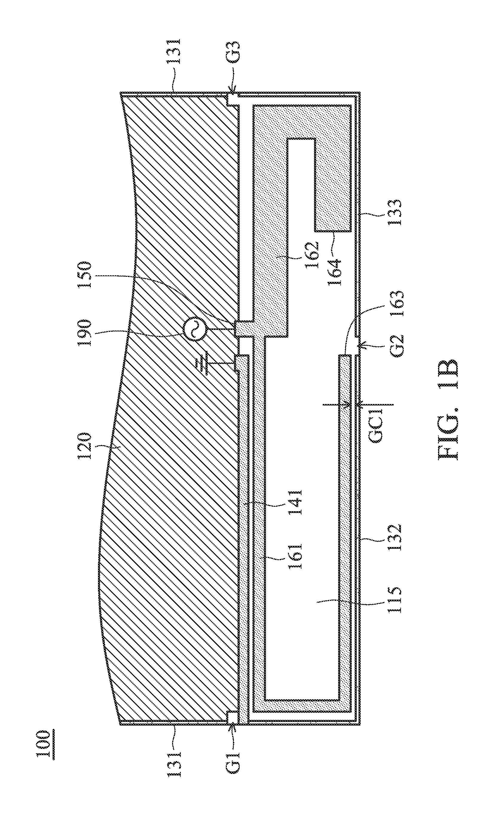
[0016]FIG. 1A is a perspective view for illustrating a mobile device 100 according to an embodiment of the invention. FIG. 1B is a top view for illustrating the mobile device 100 according to an embodiment of the invention. Please refer to FIG. 1A and FIG. 1B together. The mobile device 100 may be a smart phone or a tablet computer. As shown in FIG. 1A and FIG. 1B, the mobile device 100 at least comprises a dielectric substrate 110, a ground element 120, a first conductive frame 131, a second conductive frame 132, a third conductive frame 133, a first shorting element 141, a feeding element 150, a first radiation element 161, a second radiation element 162, and a signal source 190. The dielectric substrate 110 may be a system circuit board or an FR4 (Flame Retardant 4) substrate. The ground element 120 may be a groun...


PUM


Abstract

A mobile device includes a dielectric substrate, a ground element, a signal source, a first conductive frame, a second conductive frame, a third conductive frame, a shorting element, a feeding element, a first radiation element, and a second radiation element. The first conductive frame, the second conductive frame, and the third conductive frame are separate from each other. The second conductive frame is coupled through the shorting element to the ground element. The first radiation element is coupled to the feeding element. An open end of the first radiation element is adjacent to the second conductive frame. The second radiation element is coupled to the feeding element. An open end of the second radiation element is adjacent to the third conductive frame. An antenna structure is formed by the feeding element, the first radiation element, the second radiation element, the shorting element, and the second conductive frame.

Description

CROSS REFERENCE TO RELATED APPLICATIONS[0001]This Application claims priority of Taiwan Patent Application No. 102128046 filed on Aug. 6, 2013, the entirety of which is incorporated by reference herein.BACKGROUND OF THE INVENTION[0002]1. Field of the Invention[0003]The disclosure generally relates to a mobile device, and more particularly, to a mobile device with an antenna structure formed by conductive frames.[0004]2. Description of the Related Art[0005]With the progress of mobile communication technology, portable electronic devices, for example, portable computers, mobile phones, tablet computers, multimedia players, and other hybrid functional mobile devices, have become more common To satisfy user demand, portable electronic devices can usually perform wireless communication functions. Some functions cover a large wireless communication area, for example, mobile phones using 2G, 3G, and LTE (Long Term Evolution) systems and using frequency bands of 700 MHz, 850 MHz, 900 MHz, 1...

Claims


Application Information

Patent Timeline
Patent Type & Authority Applications(United States)
IPC IPC(8): H01Q1/24
CPCH01Q1/243H01Q9/42H01Q5/371H01Q5/385
Inventor CHANG, CHIH-HUAHUANG, SHAO-YULIN, HSIEN-CHANG
Owner ACER INC
Features
  • Generate Ideas
  • Intellectual Property
  • Life Sciences
  • Materials
  • Tech Scout
  • Unparalleled Data Quality
  • Higher Quality Content
  • 60% Fewer Hallucinations
Learn More