
Lane departure warning system and method

a technology of lane departure warning and lane detection, applied in the field of vehicles, can solve the problems of difficult identification of real road marker edge pixels to determine a lane, inability to effectively detect real lane markers, etc., to achieve the effect of effectively finding an roi and simplifying the procedure of lane detection

Active Publication Date: 2015-05-07
ULSEE
View PDF2 Cites 18 Cited by
  • Summary
  • Abstract
  • Description
  • Claims
  • Application Information

AI Technical Summary

Benefits of technology

The objective of this patent is to provide a system and method for detecting edge pixels and identifying real road marker edge pixels in order to determine a lane and find an ROI to simplify the process of lane detection. This technology can be effective even when there is no obvious gradient change, light reflection, or obstacles present.

Problems solved by technology

However, in most cases, a real lane marker cannot be detected and determined.
For example, in a case where the gradient change is not obvious, the edge detection cannot effectively detect the lane marker.
In addition, in a case where light is reflected or an obstacle exists, although edge pixels can be detected, it is very difficult to identify real road marker edge pixels to determine a lane.
In many cases, although the road marker edge pixels can be correctly detected, some complicated steps are further needed to infer the lane from the edge pixels.
For example, as for a wider lane marker, because the edge detection can only detect the edge pixels, pixels in the lane marker may be classified as non-edge pixels, and there are some difficulties in inferring the correct lane according to edge pixels on the left and right sides of the lane marker.
In addition, as for such conditions as a short lane and a channelizing line, the conventional edge detection algorithm also cannot perform effective processing.
However, most of these complicated procedures are time-consuming.
However, in many cases, the lane may often appear in the non-ROI areas.
As a result, the system cannot detect the lane.

Method used


Image

  • Lane departure warning system and method
  • Lane departure warning system and method
  • Lane departure warning system and method

Examples


Embodiment Construction

[0030]To make a person of ordinary skill in the art further understand the present invention, the following lists preferred embodiments of the present invention, and with reference to the accompanying drawings, describes in detail constituted content and efficacy to be achieved of the present invention.

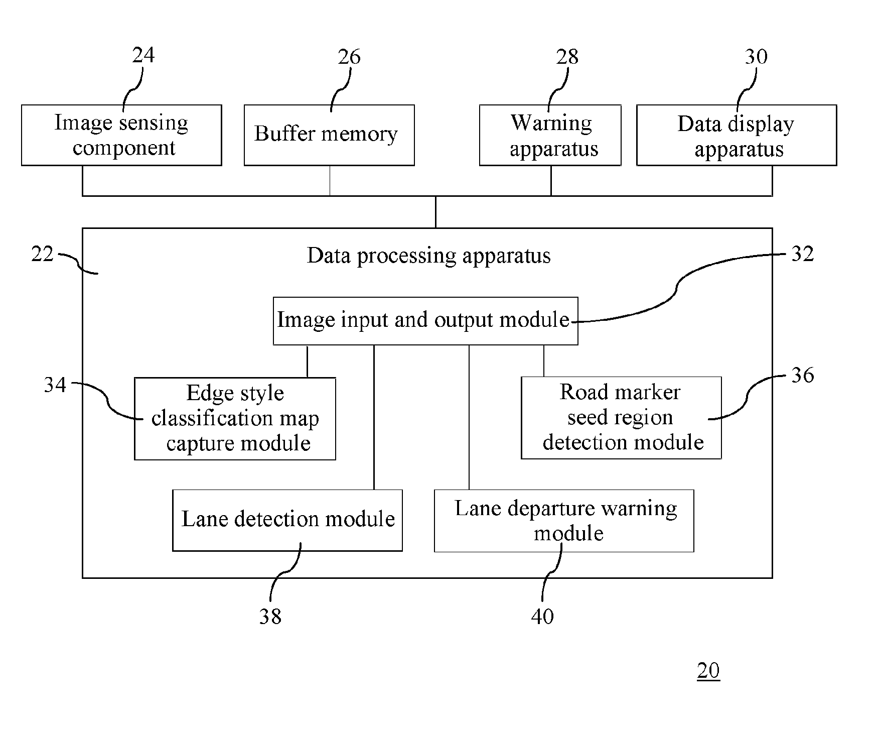
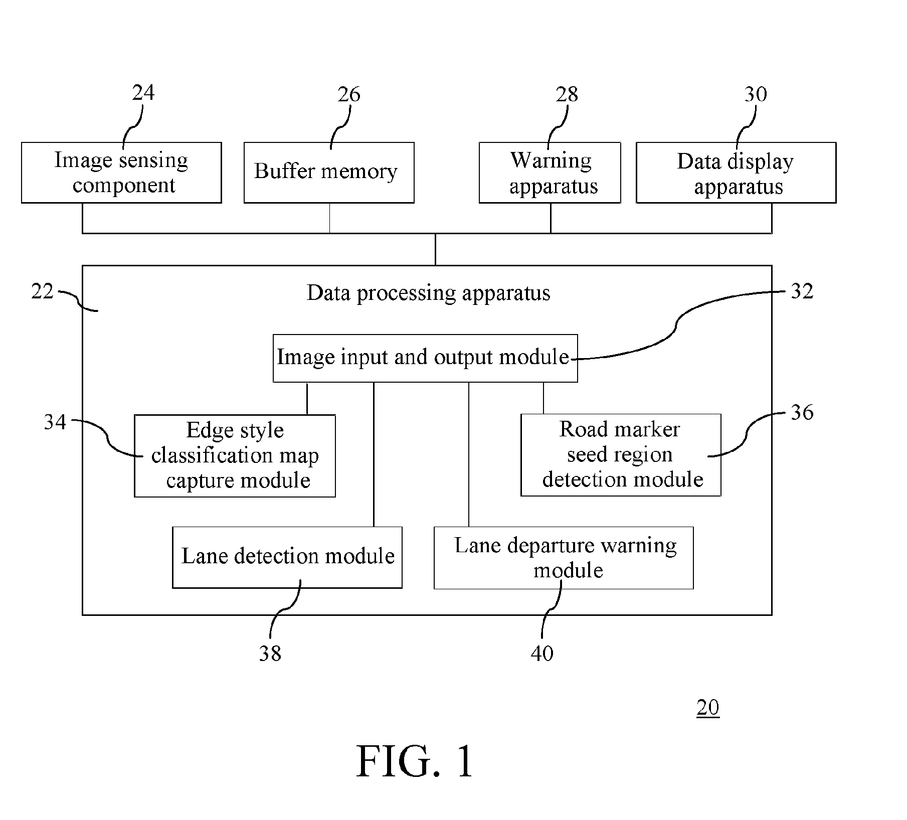
[0031]FIG. 1 is a block diagram of a lane departure warning system according to the present invention. In FIG. 1, the lane departure warning system 20 includes a data processing apparatus 22, an image sensing component 24, a buffer memory 26, a warning apparatus 28, and a data display apparatus 30. The data processing apparatus 22 may be a program library, which may be executed by a CPU; and may also be a hardware accelerator, which improves execution efficiency of the lane departure warning system 20.

[0032]The data processing apparatus 22 includes an image input and output module 32, an edge style classification map capture module 34, a road marker seed region detection module 36, a ...


PUM


Abstract

Provided is a lane departure warning system and method. The lane departure warning system includes an edge style classification map capture module, a road marker seed region detection module, a lane detection module, and a lane departure warning module, which can detect, by using an edge style classification map, and through road marker seed region detection and lane detection, lane edge pixels and identify real road marker edge pixels under a circumstance that there is no obvious gradient change or light is reflected or an obstacle exists, thereby determining a complete lane, and effectively finding a Region Of Interest (ROI) to simplify a procedure of lane detection.

Description

REFERENCE TO RELATED APPLICATION[0001]This application claims priority from Taiwanese Patent Application No. 102139923, filed on Nov. 4, 2013. The entire content of the Taiwanese application is hereby incorporated by reference into this application.BACKGROUND OF THE INVENTION[0002]1. Field of the Invention[0003]The present invention relates to the technical field of vehicles, and in particular, to a lane departure warning system and method for vehicles.[0004]2. Related Art[0005]At the present stage, a lane detection algorithm mainly includes two steps: edge detection and line detection, which are mainly applied to detecting a manual lane marker.[0006]In a conventional edge detection algorithm, in a general case (when there is only a simple lane marker with an obvious gradient change, and there are no other complicated situations, such as vehicles, shadows, man-made objects, and trees), a lane marker may be successfully detected and determined. However, in most cases, a real lane mar...

Claims


Application Information

Patent Timeline
Patent Type & Authority Applications(United States)
IPC IPC(8): G06K9/00G06K9/46
CPCG06K9/00798G06K9/00536G06K9/4604G06V20/588G06F2218/12
Inventor WU, YI-TSUNG
Owner ULSEE
Learn More