Machine for sawing trenches and placing ducts/cables

a technology of ducts/cables and sawing machines, which is applied in the direction of metal sawing apparatus, pipe laying and repair, instruments, etc., can solve the problems of changing the angle the temperature of the saw blade can increase so much, and the damage of the saw blade, so as to reduce the friction of the saw blad

Inactive Publication Date: 2015-05-07
DELLCRON
View PDF5 Cites 26 Cited by
  • Summary
  • Abstract
  • Description
  • Claims
  • Application Information

AI Technical Summary

Benefits of technology

[0005]An object of the present invention is to provide a machine for sawing micro trenches and placing ducts / communication cables which fully or in part solves the problems and drawbacks of prior art. Another object of the present invention is to provide a sawing machine which reduces the friction of the saw blade when sawing micro trenches.
[0010]The machine according to the present invention makes it possible to control the saw angle of the saw blade relative to the ground thereby reducing the friction when sawing trenches. This saves money since the lifespan of each saw blade can be prolonged. Further, the vertical height of the machine can also be controlled with the present invention which means that suitable sawing height can easily be obtained. It is therefore realised that the arrangement of individually vertically adjustable wheels gives plural advantages over prior art.

Problems solved by technology

In a few seconds the temperature of the saw blade can increase so much that the saw blade is destroyed due to the heat long before it is mechanically worn out.
This may happen if the ground surface on which the sawing machine is moving forward is uneven.
Such unevenness may result in that the sawing machine leans a few degrees from one side to the other (perpendicular to the sawing direction) and thereby changing the saw blade angle.

Method used


Image

  • Machine for sawing trenches and placing ducts/cables
  • Machine for sawing trenches and placing ducts/cables
  • Machine for sawing trenches and placing ducts/cables

Examples


Embodiment Construction

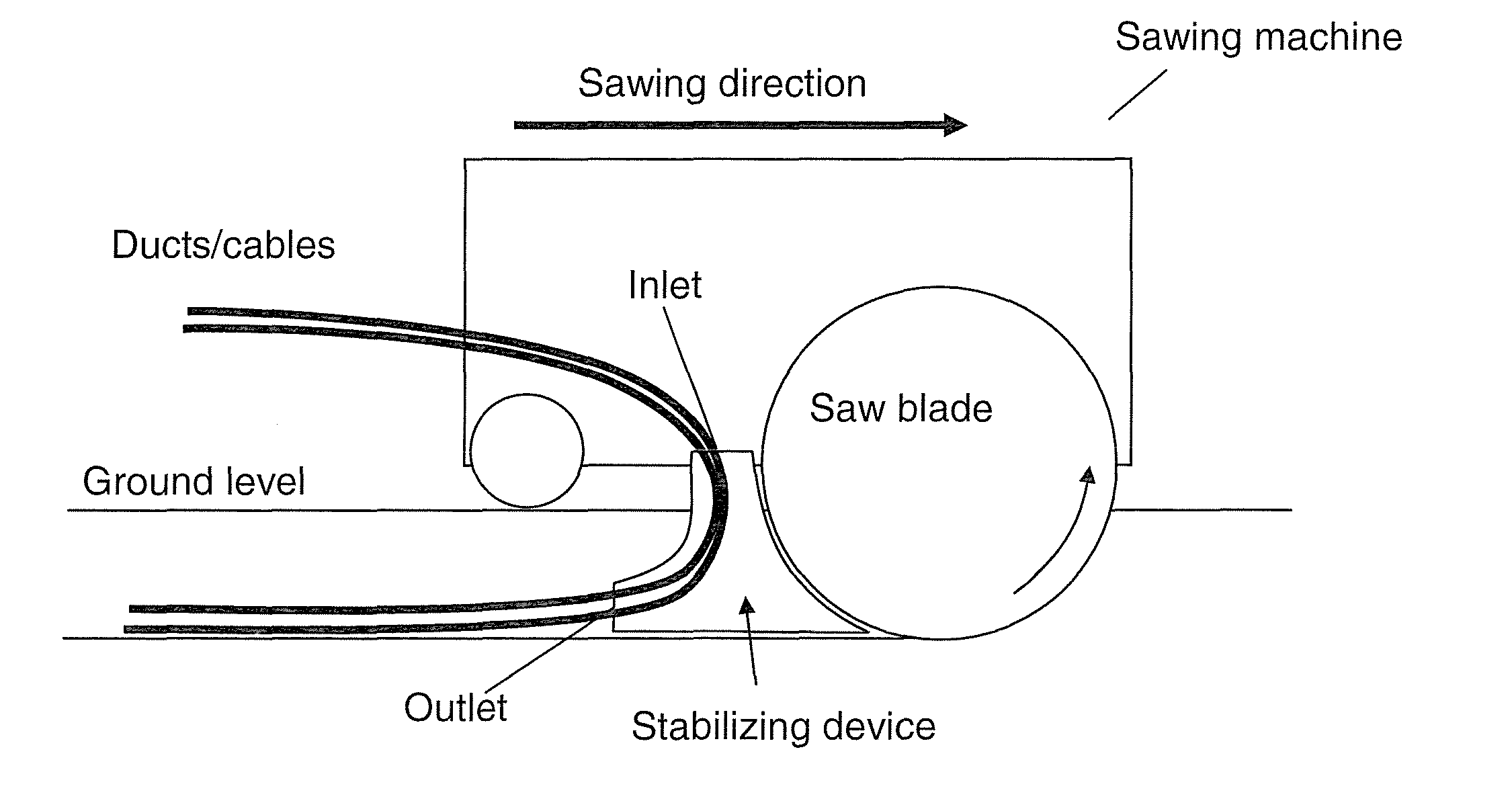
[0025]To solve the aforementioned and other problems, the present invention relates to a sawing machine comprising a saw blade arranged for sawing micro trenches in an area. The machine further comprises a stabilizing device arranged for stabilizing the walls of the micro trenches when placing ducts / cables into the same. Moreover, the stabilizing device is positioned immediately behind the saw blade in the micro trench and comprises guiding means for guiding at least one duct / cable when placed into the micro trench. Furthermore, the sawing machine comprises at least three wheels for driving the machine, and the wheels are individually vertically adjustable so that a height and / or tilting of the machine relative to ground can be controlled. Thereby, with a fixed mounted sawing blade its angle relative to ground can be controlled and hence reducing friction when sawing trenches. Another advantage of the present invention is that the height of the machine above ground can also be contr...


PUM

PropertyMeasurementUnit
distanceaaaaaaaaaa
distanceaaaaaaaaaa
distanceaaaaaaaaaa

Abstract

The present invention relates to a machine arranged for sawing micro trenches and placing ducts / cables in micro trenches, said machine comprising a saw blade arranged for sawing a micro trench in an area; said machine further comprising: a stabilizing device arranged for stabilizing the walls of said micro trench when placing ducts / cables into said micro trench, said stabilizing device being positioned immediately behind said saw blade in said micro trench, and said stabilizing device comprising guiding means for guiding at least one duct / cable when placed into said micro trench; at least three wheels for driving said machine, wherein said wheels are individually vertically adjustable so that a height and / or tilting of said machine relative to ground can be controlled.

Description

TECHNICAL FIELD[0001]The present invention relates to a machine for sawing micro trenches and placing ducts / cables in trenches. More specifically, the invention relates to a machine according to claim 1.BACKGROUND OF THE INVENTION[0002]Micro Trenching is expected to become the dominating method for building Fiber-To-The-Home (FTTH) in areas with detached or semi-detached houses. In Sweden around 400 000 houses are expected to be connected to a fiber network during the next 5-10 years. The world market is enormous and may be estimated to around 100-500 times the Swedish market. This means that somewhere between 40 million to 200 million houses may be connected during the next 20 years.[0003]When placing ducts and / or cables in micro trenches a (road) sawing machine is used for sawing trenches in which the ducts / cables are placed. Therefore, crucial for the economy when building FTTH using micro trenching is the lifespan of the saw blade that is used for sawing the trench. As engines w...

Claims


Application Information

Patent Timeline
Patent Type & Authority Applications(United States)
IPC IPC(8): E02F5/14B23D45/00E02F9/00E02F5/12E02F5/02F16L1/028
CPCE02F5/145E02F5/02B23D45/003E02F9/00E02F5/12F16L1/028F16L1/032H02G1/06E02F5/08H02G9/02G02B6/504E02F5/10
Inventor GUSTAVSSON, CONNYHULTMAN, HASSE
Owner DELLCRON
Why Eureka
Try Eureka