Bone screw fastener

a bone screw and fastener technology, applied in the field of bone screw fasteners, can solve the problem of lower pull out force required to tear through the threads in the bone, and achieve the effect of enhancing the resistance to thread loosening

Active Publication Date: 2015-05-07
BONE PHARM LLC
View PDF2 Cites 11 Cited by
  • Summary
  • Abstract
  • Description
  • Claims
  • Application Information

AI Technical Summary

Benefits of technology

[0008]An improved bone screw for humans or mammals is a bone screw having exposed surfaces along a shank and threads extending from the shank with one or more selected portions of the exposed surfaces having a 3-dimensional pattern. The pattern provides enhanced resistance to thread loosening when affixed to bone. The exposed surface is on exterior portions of the threads or portions of the shank or both. The one or more selected portions of the exposed portions having a bone formation enhancing 3-dimensional patterns are in the external exposed thread surfaces or in the exposed shank surfaces or both.

Problems solved by technology

Secondarily, when the screw loosens it can also lower the pull out forces required to tear through the threads in the bone.

Method used


Image

  • Bone screw fastener
  • Bone screw fastener
  • Bone screw fastener

Examples


Embodiment Construction

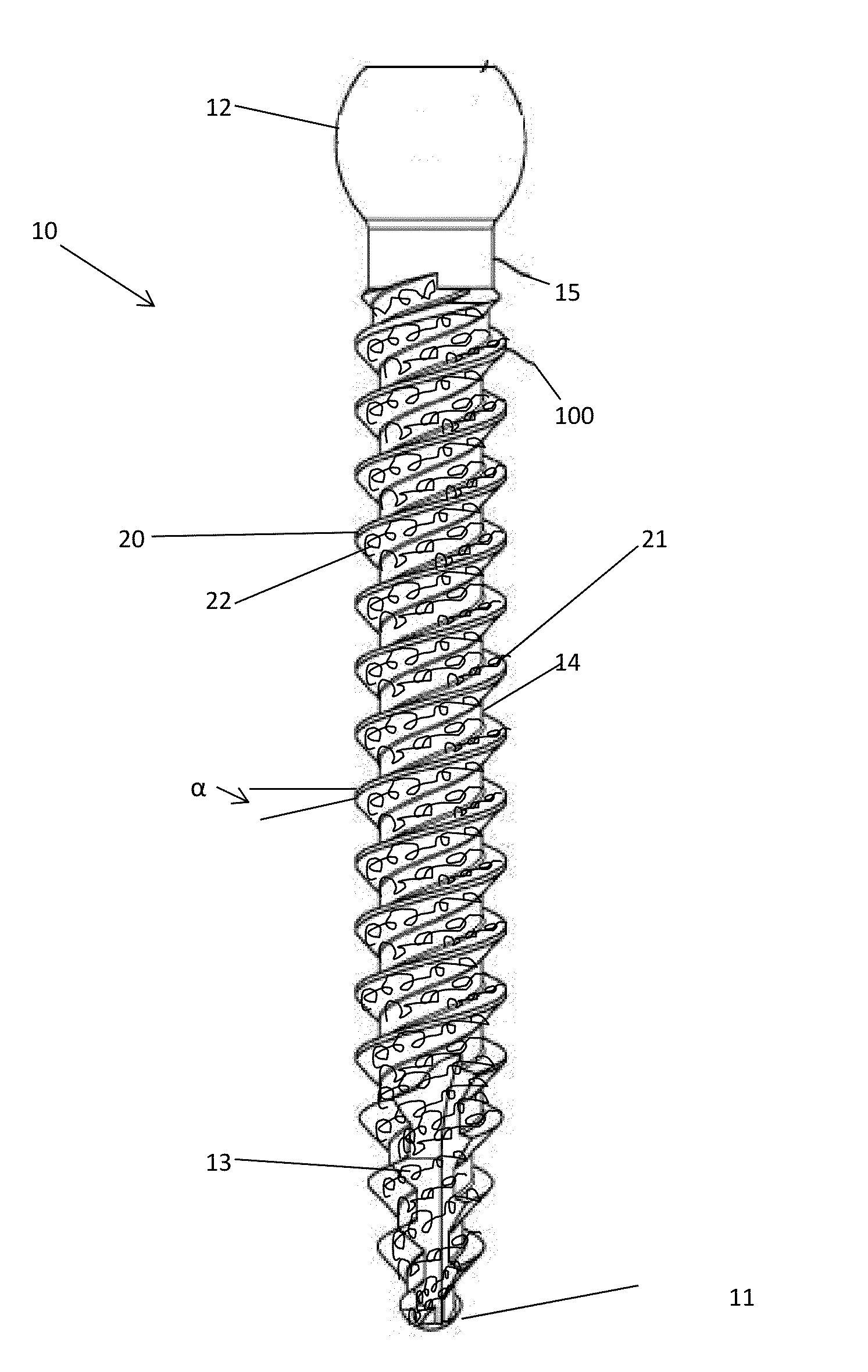
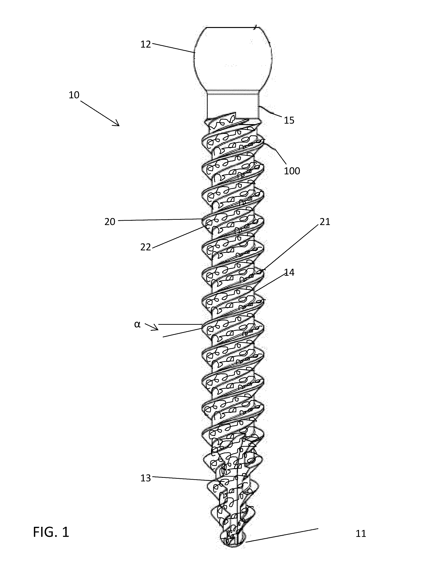
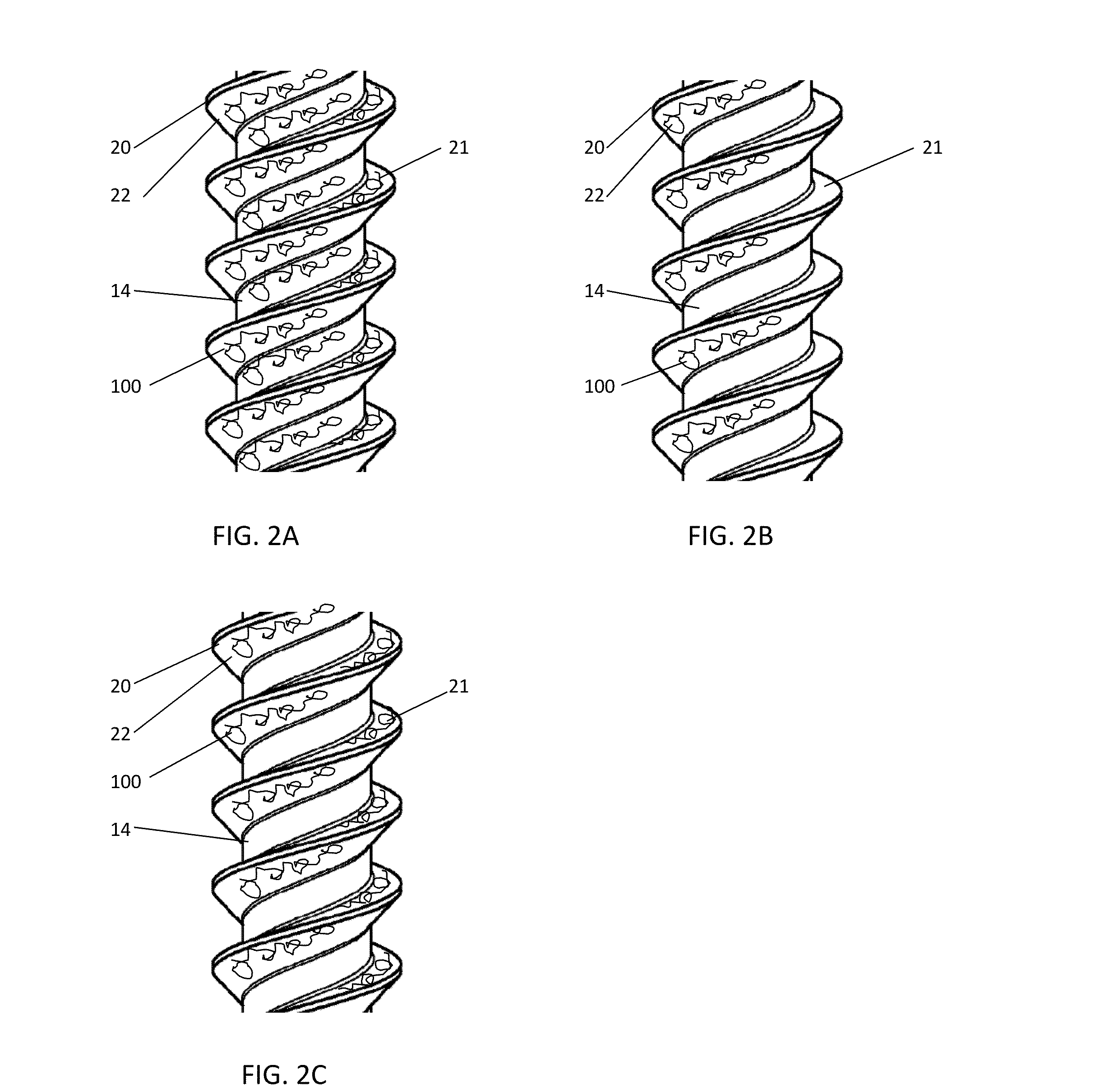
[0022]With reference to FIG. 1, an exemplary bone screw 10 made in accordance with the present invention is illustrated. As shown, the bone screw 10 has a proximal tip end 11. As shown, the proximal tip end 11 has bone cutting flutes 13 to facilitate insertion of the bone screw 10 into a skeletal bone structure. As illustrated, the bone screw 10 has a shank 14. Radially extending outwardly from the shank 14 is a thread 20, the thread 20 can be one or more threads spirally wound about the shank 14 wherein the proximal surface 22 is on the underside of the thread 20 as shown and the distal surface 21 of the thread 20 is on an outer or upper surface of the thread 20 as it spirals about the shank 14. At the opposite end of the screw 10 is shown a screw head 12. In the illustrated embodiment, this screw head 12 has a shoulder 15 that allows the screw head 12 which has a somewhat spherical configuration to operate in a polyaxial fashion when mounted to a conventionally known tulip, not il...


PUM

PropertyMeasurementUnit
widthaaaaaaaaaa
depthaaaaaaaaaa
widthaaaaaaaaaa

Abstract

An improved bone screw for humans or mammals is a bone screw having exposed surfaces along a shank and threads extending from the shank with one or more selected portions of the exposed surfaces having a 3-dimensional pattern. The pattern provides enhanced resistance to thread loosening when affixed to bone. The exposed surface is on exterior portions of the threads or portions of the shank or both. The one or more selected portions of the exposed portions having a bone formation enhancing 3-dimensional patterns are in the external exposed thread surfaces or in the exposed shank surfaces or both.

Description

RELATED APPLICATIONS[0001]This application is a continuation in part of co-pending U.S. application Ser. No. 13 / 737,043 filed Jan. 9, 2013 entitled, “Bone Implants And Method Of Manufacture” which is a division of U.S. Pat. No. 8,414,654 filed on Nov. 23, 2011 entitled, “Bone Implants And Method Of Manufacture”.TECHNICAL FIELD[0002]The present invention relates to an improved bone screw having an externally prepared surface characteristic to prevent loosening while simultaneously encouraging new bone growth.BACKGROUND OF THE INVENTION[0003]Bone screws are provided in a variety of shapes and sizes. The most common employ titanium or stainless steel as a preferred material for implantation. These screws are ideal in that they do not oxidize and are very compatible with the bone structure. These screws typically employ one or more helical threads. Many are self-tapping at the proximal tip or end. The distal end of the screw has a head or some physical construction to allow torqueing th...

Claims


Application Information

Patent Timeline
Patent Type & Authority Applications(United States)
IPC IPC(8): A61B17/86A61F2/30A61B17/70
CPCA61B17/8625A61F2/30767A61B17/7098A61B17/866A61C8/0012A61F2/28A61F2002/2835Y10T29/49Y10T29/49746
Inventor GANEY, TIMOTHY
Owner BONE PHARM LLC
Why Eureka
Try Eureka