
Reliable Arc Fault Circuit Interrupter Tester Utilizing A Dynamic Fault Voltage

a dynamic fault voltage and fault voltage technology, applied in the field of systems and methods for testing arc fault circuit interrupters, can solve problems such as shortening the local power distribution system

Active Publication Date: 2015-05-14
UNIQUE TECH
View PDF12 Cites 14 Cited by
  • Summary
  • Abstract
  • Description
  • Claims
  • Application Information

AI Technical Summary

Benefits of technology

The technical effect of this patent is to provide a system, device, and method for testing an AFCI to accurately determine its functional state.

Problems solved by technology

Each control pulse causes the power transistor to couple the hot line to the neutral line, thereby shorting the local power distribution system.

Method used


Image

  • Reliable Arc Fault Circuit Interrupter Tester Utilizing A Dynamic Fault Voltage
  • Reliable Arc Fault Circuit Interrupter Tester Utilizing A Dynamic Fault Voltage
  • Reliable Arc Fault Circuit Interrupter Tester Utilizing A Dynamic Fault Voltage

Examples


Embodiment Construction

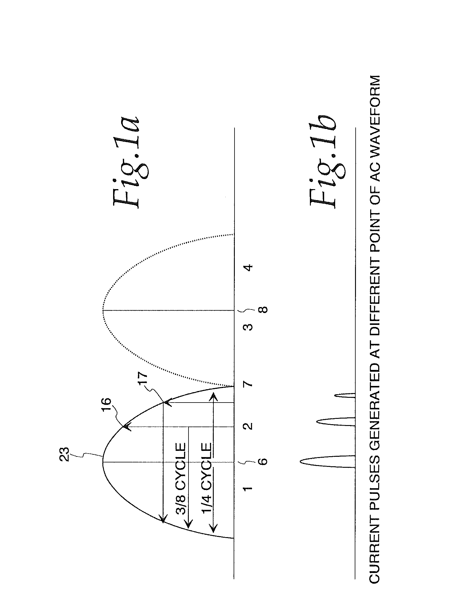
[0017]Turning to the Figures, and to FIG. 1a in particular, a single phase 10 of an AC power system is depicted. In a standard AC power system an idealized power line waveform will be sinusoidal. When passed through a full-wave bridge rectifier, however, the rectified power waveform will comprise a series of positive half-cycles. A full cycle of rectified AC power can be broken into four quadrants, as shown in FIG. 1a. Quadrants 1 and 2 are identical to the non-rectified AC waveform; i.e., the first quadrant consists of rising voltages until a peak is reached at point 6, which starts the second quadrant that consists of falling voltages until, in an ideal system (without any voltage drops across diodes), zero voltage is reached at point 7. However, in a standard power system, voltages would continue passing through 0 Volts to a negative voltage. The rectified waveform shown in FIG. 1a, however, essentially repeats the first half cycle in the second half cycle, so that quadrant 3 is ...


PUM


Abstract

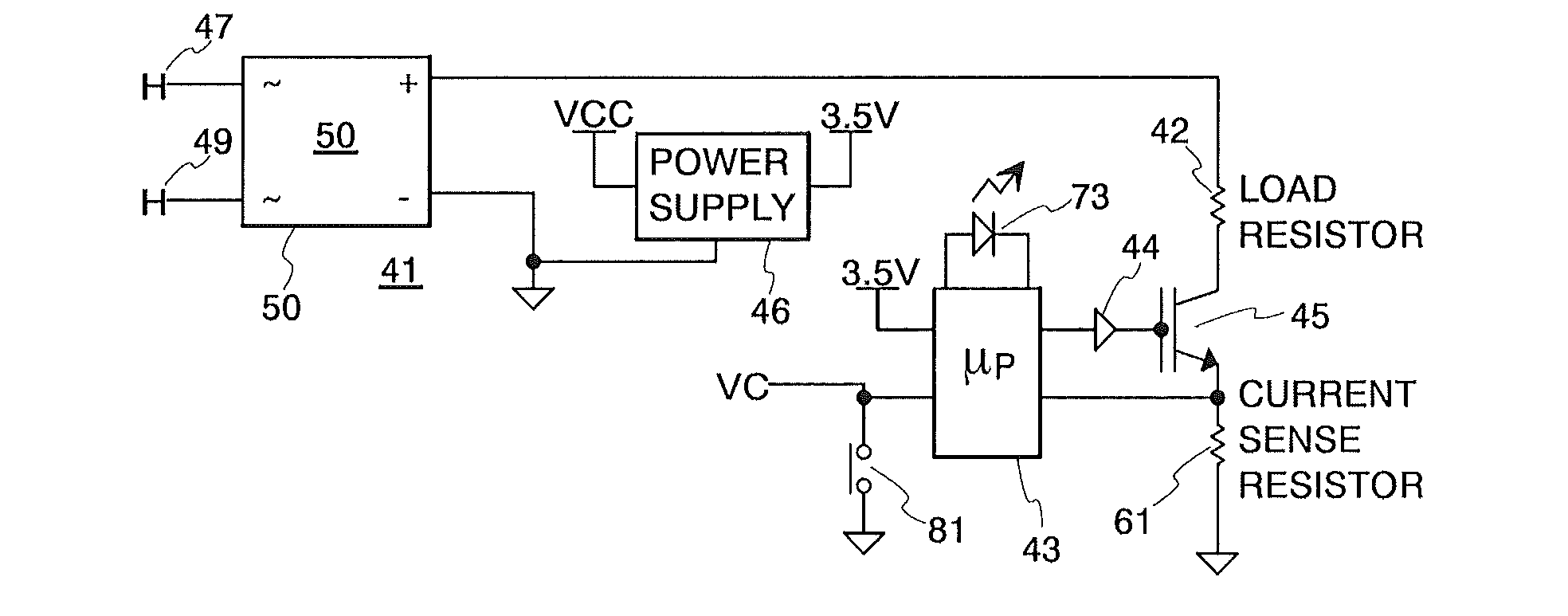
An arc fault circuit interrupter test circuit is disclosed. The test circuit incorporates a controller along with at least one power transistor, a current sense circuit and a voltage sense circuit. When the power transistor is operated, the current flowing through the transistor is sensed, and if the current is not at least equal to a threshold value, the voltage at which the power transistor is operated is increased.

Description

CLAIM OF PRIORITY TO RELATED APPLICATION[0001]This is a continuation of U.S. patent application Ser. No. 13 / 080,746, entitled “Arc Fault Circuit Interrupter Tester With Current Responsive Pulse Timing,” filed on Apr. 6, 2011 in the names of inventors Kerry Berland, Paul Berland, and Mitch Budniak and assigned to Unique Technologies, Inc.FIELD OF THE INVENTION[0002]The present invention relates generally to systems and methods for testing arc fault circuit interrupters and is particularly directed to a test instrument for testing the efficacy of arc fault circuit interrupter installed in electrical distribution circuits and a method of operating the aforementioned test instrument.DESCRIPTION OF THE PRIOR ART[0003]Circuit breakers interrupt the flow of current after detecting a fault condition in a monitored circuit. Fault conditions can by caused by numerous circuit conditions. Over current faults, for example, are usually caused by a short condition somewhere within a distribution c...

Claims


Application Information

Patent Timeline
Patent Type & Authority Applications(United States)
IPC IPC(8): G01R31/07G01R31/74
CPCG01R31/07G01R31/3277G01R31/52G01R31/58G01R31/74
Inventor BERLAND, KERRYBERLAND, PAULBUDNIAK, MITCH
Owner UNIQUE TECH
Learn More