Liquid ejection head and method of producing the same

a technology of liquid ejection and liquid ejection, which is applied in the direction of printed circuits, printing, electrical apparatus, etc., can solve the problems of difficult to bend the electrical wiring board completely along the shape of the housing, the liquid film boiling, and the electrical wiring board is difficult to completely bend the electrical wiring board, etc., to achieve the effect of suppressing the protrusion

Active Publication Date: 2015-05-14
CANON KK
View PDF0 Cites 13 Cited by
  • Summary
  • Abstract
  • Description
  • Claims
  • Application Information

AI Technical Summary

Benefits of technology

[0009]The present invention has an object to provide a liquid ejection head and a method of producing the liquid ejection head, which are capable of suppressing protrusion due to lifting of an electrical wiring board fixed to a housing.

Problems solved by technology

The liquid droplets are ejected by heating the liquid by an energy-generating element including a heat generating resistor, thereby causing film boiling in the liquid.
The main portion of the electrical wiring board, in particular, a bent portion is made of a flexible material such as a flexible wiring board, but it is difficult to bend the electrical wiring board completely along the shape of the housing.
The lifting of the electrical wiring board occurs not only during production but also due to heat after usage and change over the years.
The increase in the interval L causes problems such as printing failure and paper jam due to reduction of the effect to press the sheet by the sheet pressing rollers 61a and 61b.
The paper jam often occurs if the sheet is unsatisfactory pressed particularly when the sheet enters the space below the liquid ejection head 1 during sheet feeding.
In this case, however, the electrical wiring board is fixed under a tensioned state, and hence a crimped part of the electrical wiring board may be cracked after the tension is released, or another part thereof may be wrinkled.
Therefore, the above-mentioned problems cannot be solved.

Method used


Image

  • Liquid ejection head and method of producing the same
  • Liquid ejection head and method of producing the same
  • Liquid ejection head and method of producing the same

Examples


first embodiment

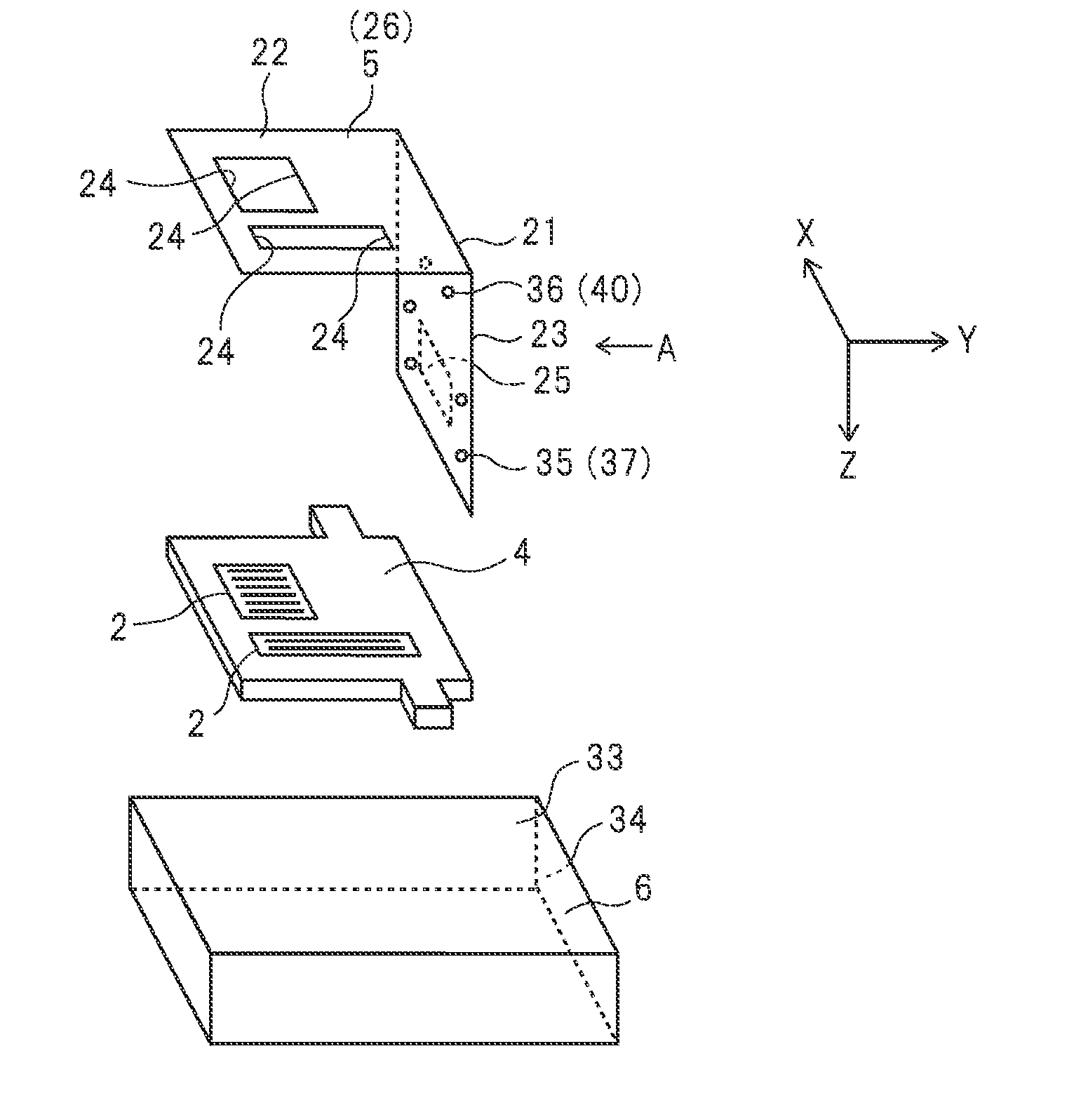
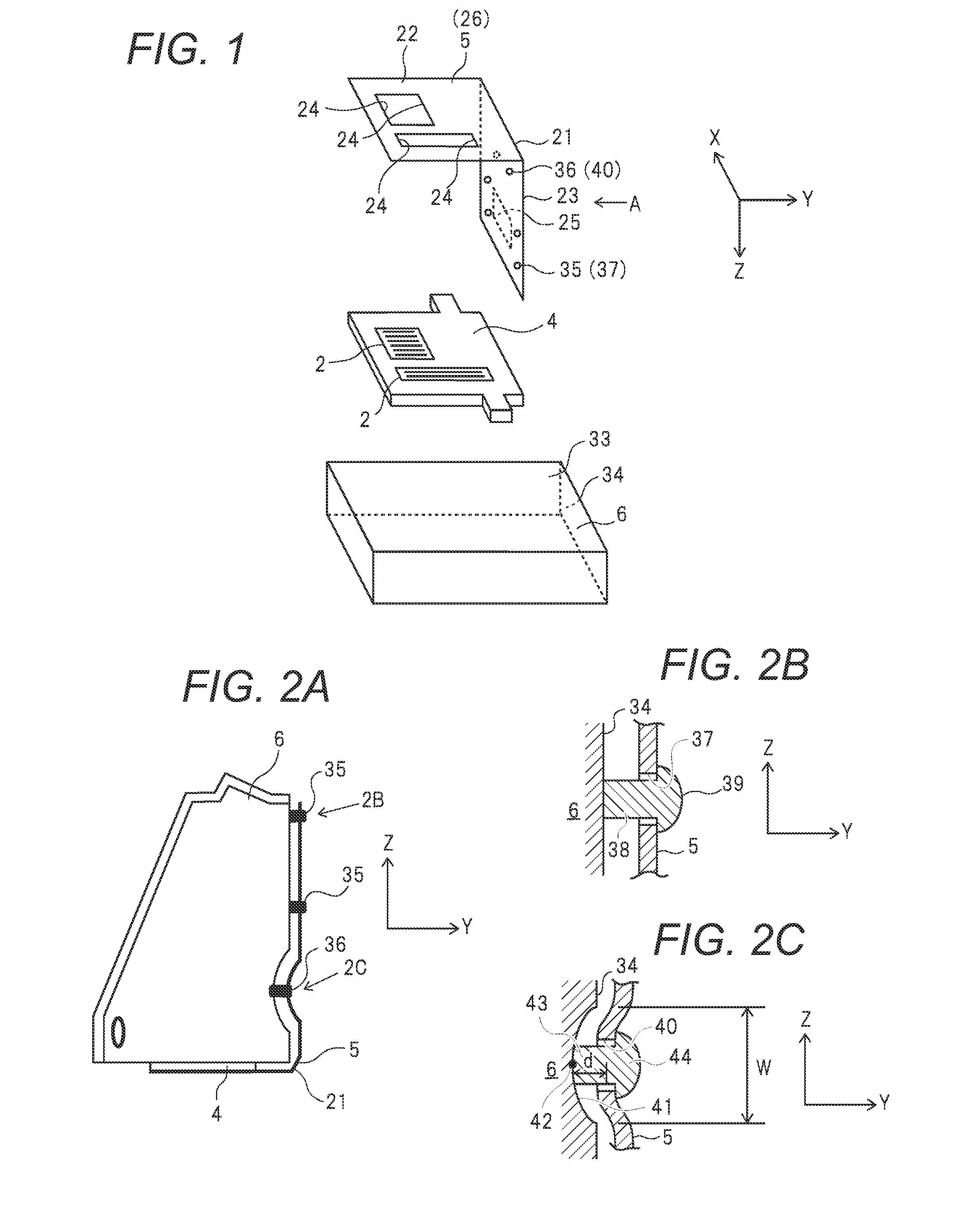
[0048]FIG. 1 is a main part exploded perspective view of a liquid ejection head 1. FIG. 2A is a main part side view of the liquid ejection head 1 (upside down with respect to FIG. 1), and FIGS. 2B and 2C are enlarged views of the part 2B and the part 2C of FIG. 2A, respectively. The liquid ejection head 1 includes a recording element substrate 2 for ejecting liquid in response to an electrical signal, a support member 4 for supporting the recording element substrate 2, an electrical wiring board 5, and a housing 6 for supporting the support member 4 and the electrical wiring board 5.

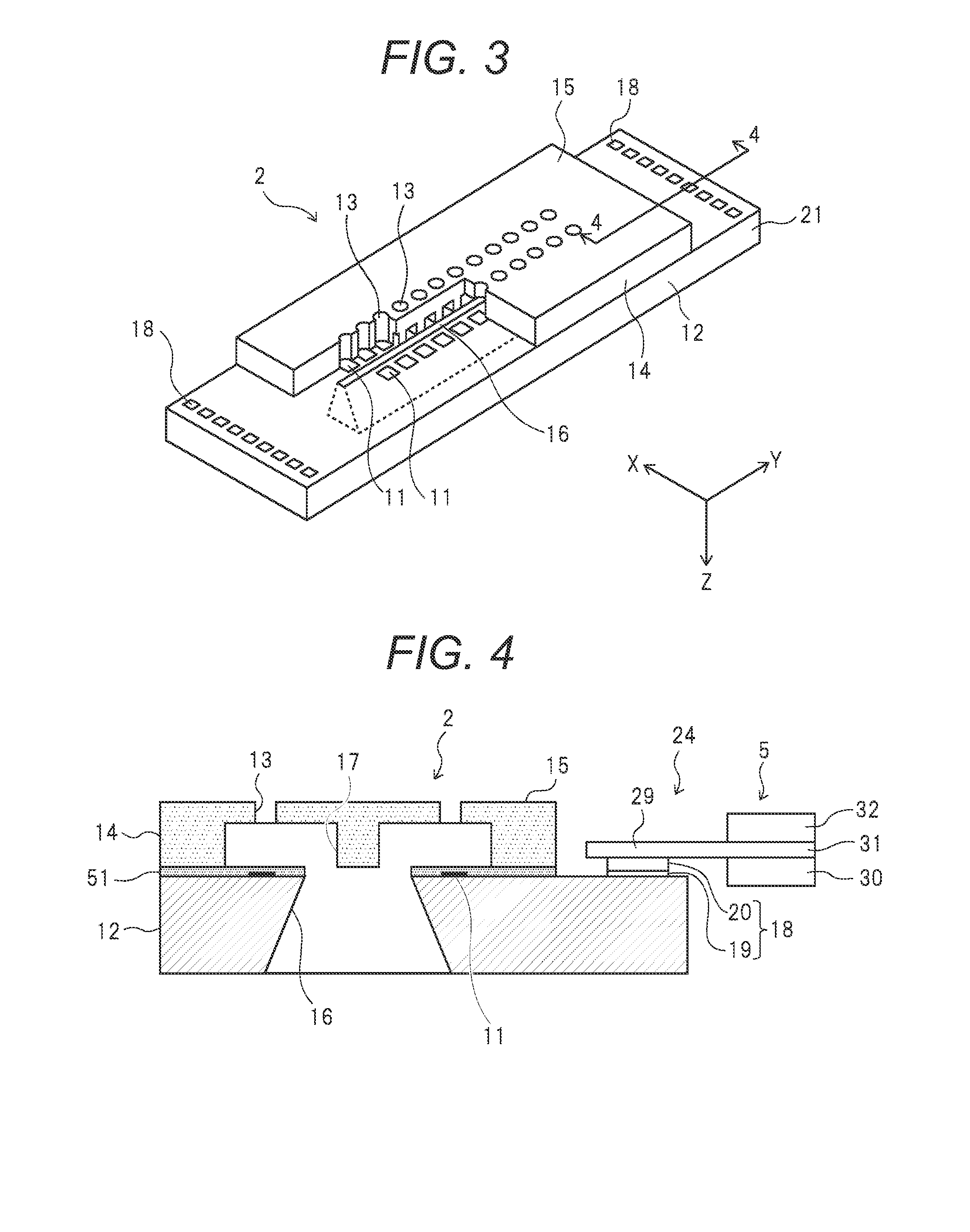
[0049]FIG. 3 is a perspective view of the recording element substrate 2, and FIG. 4 is a sectional view taken along the line 4-4 of FIG. 3. The recording element substrate 2 includes a silicon support substrate 12 having energy-generating elements 11 each including a heat generating resistor formed thereon, and an ejection-orifice-forming member 14 including a plurality of ejection orifices 13 and coveri...

second embodiment

[0071]With reference to FIG. 9, a second embodiment of the present invention is described. In this embodiment, there is only one second fixing position 36. The one second fixing position 36 is located on the center line 39 of the electrical wiring board 5, which extends in the direction orthogonal to the bent portion 21. First, the electrical wiring board 5 is crimped at the first fixing positions 35 by a method similar to that in the first embodiment, and then the electrical wiring board 5 is crimped at the second fixing position 36 by a method similar to that in the first embodiment. Other features relating to the configuration, the used members, and the producing method of the ink jet liquid ejection head 1 are the same as those in the first embodiment.

third embodiment

[0072]With reference to FIGS. 10A and 10B, a third embodiment of the present invention is described. In this embodiment, the electrical wiring board 5 is first fixed at the second fixing position 36, and then is fixed at the first fixing positions 35. First, by a method similar to that in the first embodiment, the electrical wiring board 5 is pressed into the depressed portion 41 so that the electrical wiring board 5 follows the shape of the depressed portion 41 of the housing 6, and the pin 43 is aligned to the opening 40 at the second fixing position 36. Simultaneously therewith, by a method similar to that in the first embodiment, the pins 38 are aligned to the openings 37 at the first fixing positions 35, respectively. As illustrated in FIG. 10A, under a state in which the electrical wiring board 5 is pressed so as to follow the shape of the depressed portion 41 of the housing 6, by a method similar to that in the first embodiment, the electrical wiring board 5 is first crimped ...


PUM

PropertyMeasurementUnit
electricalaaaaaaaaaa
flexibleaaaaaaaaaa
energyaaaaaaaaaa

Abstract

A liquid ejection head, including a recording element substrate for ejecting liquid in response to an externally supplied electrical signal; an electrical wiring board having a first and second part mutually joined via a bent portion, the first part having an electrical joint portion for supplying the signal to the substrate, the second part having an electrical signal input portion into which the signal is input and to which the joint portion is connected; and a housing having a first and second surface mutually adjoining, the first and second surfaces respectively supporting the first and second parts. The second part is fixed to the second surface at plural first fixing positions around the input portion. The second surface has a depressed portion formed closer to the bent portion than the first fixing positions. The second part is fixed to the housing at a second fixing position inside the depressed portion.

Description

BACKGROUND OF THE INVENTION[0001]1. Field of the Invention[0002]The present invention relates to a liquid ejection head to be used in a liquid ejection apparatus for ejecting liquid such as ink to form an image or perform recording, and to a method of producing the liquid ejection head.[0003]2. Description of the Related Art[0004]A liquid ejection head forms an image by ejecting liquid droplets. The liquid droplets are ejected by heating the liquid by an energy-generating element including a heat generating resistor, thereby causing film boiling in the liquid. Alternatively, a piezoelectric element may be used sometimes to eject the liquid droplets, or a method involving irradiating the liquid with an electromagnetic wave generated by a laser or the like is also sometimes employed. Such a liquid ejection head is generally mounted on a recording apparatus main body. The liquid ejection head is controlled and driven by an electrical signal supplied from the recording apparatus main bo...

Claims


Application Information

Patent Timeline
Patent Type & Authority Applications(United States)
IPC IPC(8): B41J2/14B41J2/16
CPCB41J2/1433B41J2/1607B41J2002/14491B41J2/16B41J2/1648B41J2/14024B41J2/14072B41J2/1603B41J2/1623B41J29/02B41J29/13Y10T29/4913
Inventor KODOI, TAKUMAIWANO, TAKUYATOMIZAWA, KEIJI
Owner CANON KK
Why Eureka
Try Eureka