LED holder

Active Publication Date: 2015-05-14
MOLEX INC
View PDF27 Cites 36 Cited by
  • Summary
  • Abstract
  • Description
  • Claims
  • Application Information

AI Technical Summary

Benefits of technology

[0008]The effects of the present disclosure are as follows: the holder has the connector to mate with the mating connector so as to allow convenient assembly, and the connector and the terminal are connected via the wire, which may omit arrangement of traces so as to simplify the man

Problems solved by technology

The former is relative complicate in assembly operation since the wires are required for separate insertion; the latter is relatively convenient to a

Method used


Image

  • LED holder
  • LED holder
  • LED holder

Examples


Example

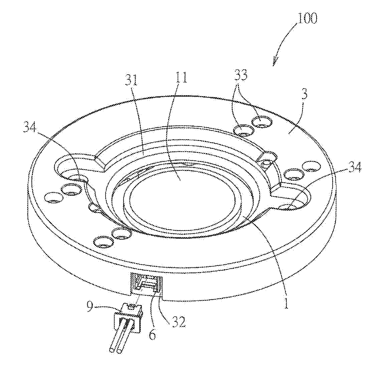
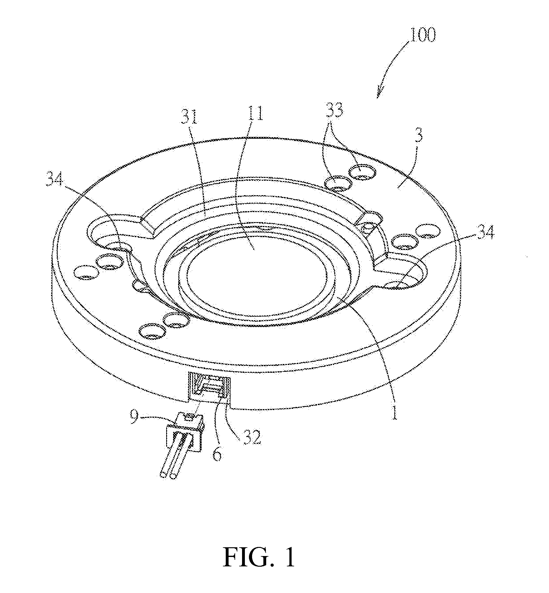
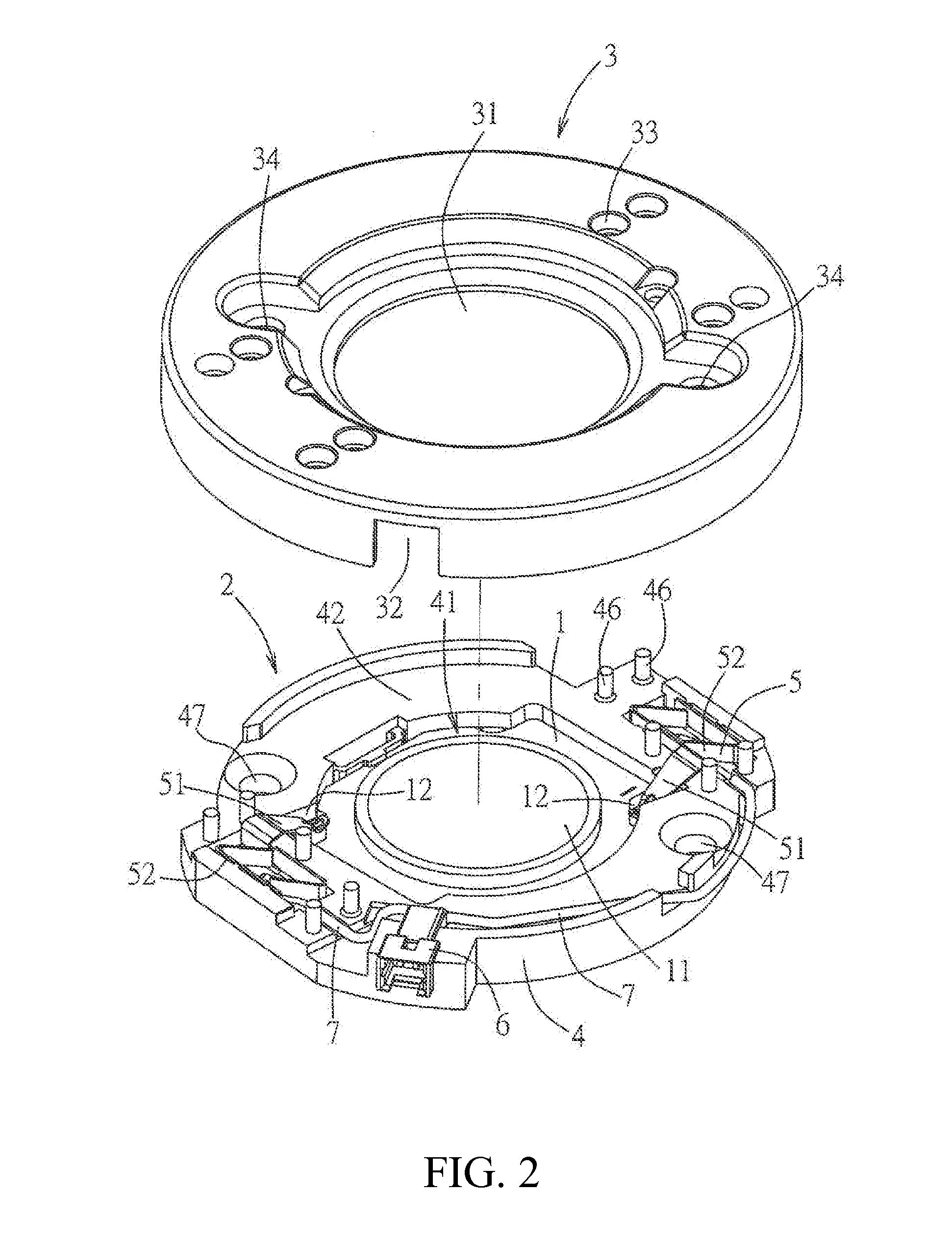
[0019]Referring to FIG. 1 and FIG. 2, a first embodiment of an illumination device 100 of the present disclosure may be use for externally connecting a mating connector 9, the illumination device 100 comprises a light emitting module 1, a holder 2 and a cover 3.

[0020]Referring to FIG. 3 through FIG. 5, the light emitting module 1 has a light emitting portion 11 and two contact pads 12, the number of the contact pads 12 may be more than two, depending on the practical requirement, and it is not limited to the embodiment. The light emitting module 1 specifically may be a light emitting module packaging a plurality of light emitting diodes dies.

[0021]The holder 2 comprises a base body 4, two terminals 5, a connector 6 and two wires 7. The base body 4 defines a receiving hole 41 for receiving the light emitting module 1, and has a top face 42, a bottom face 43 and a mounting groove 44 for receiving the connector 6. The receiving hole 41 has a window portion 411 passing through the top f...

Example

[0026]Referring to FIG. 6 through FIG. 8, a second embodiment of the illumination device 100 of the present disclosure is substantially the same as the first embodiment, however, in the second embodiment, the contact pad 12 of the light emitting module 1 is provided as four in number, the terminal 5 of the holder 2 is also correspondingly provided as four in number, and the four terminals 5 are electrically connected to the connector 6 respectively via four wires 7. Moreover, in the second embodiment, the wire insertion structure 52 of each terminal 5 is replaced as in form of insulation-displacement termination (IDT). That is, the wire insertion structure 52 has two pairs of clip pieces 523, a blade gap 524 is formed between each pair of clip pieces 523, when the wire 7 is placed into the blade gap 524, an outer insulation of the wire 7 is displaced by the clip pieces 523 at both sides of the blade gap 524, so as to allow the central metal conductor 71 (see FIG. 4) inside the wire ...


PUM


Abstract

A holder comprises a base body, at least two terminals, a connector and at least two wires. The base body defines a receiving hole for receiving the light emitting module. The terminals are provided to the base body and each have a pressing contact portion and a wire insertion structure, the pressing contact portions extend into the receiving hole and respectively press against the contact pads of the light emitting module. The connector is provided to the base body so as to externally connect a mating connector. The wires respectively correspond to the terminals to allow one end of each wire to be detachably connected to the wire insertion structure of the corresponding terminal and the other end of the each wire to be connected to the connector so that the terminals and the connector are electrically connected.

Description

RELATED APPLICATIONS[0001]This application claims priority to Taiwanese Application No. 102216709, filed Sep. 5, 2014, which is incorporated herein by reference in its entirety.FIELD OF THE PRESENT DISCLOSURE[0002]The present disclosure relates to a holder for mounting a light emitting module, and particularly relates to a holder for an illumination device and an illumination device.BACKGROUND OF THE PRESENT APPLICATION[0003]Recently, a light emitting diode (LED) has been widely applied in many fields due to its advantages of energy saving, environmental protection, long service life and the like, especially many types of products in the illumination field have been developed. One type of product is an illumination device formed by a LED module, for example, Taiwanese patent No. TWM409543 (corresponding to US2013 / 0084748A1, W02011 / 088212A2, CN201120042217.0 and CN201180004948.9) discloses a holder assembly for fixing a LED module. The LED module is formed by packaging a plurality of...

Claims


Application Information

Patent Timeline
IPC IPC(8): F21V19/00F21V21/00
CPCF21V19/0015F21Y2101/02F21V21/00F21V19/0055F21V19/004F21V23/06F21Y2105/00F21Y2105/10F21Y2115/10
Inventor HO, YI-TSE
Owner MOLEX INC
Why Eureka
Try Eureka