Industrial machine and method for measuring amount of expansion/contraction of industrial machine

a technology of industrial machines and measuring methods, which is applied in the direction of mechanical measuring arrangements, instruments, and using mechanical means, etc., can solve the problems of error in the z-axis direction of the coordinate value of the probe, and unreliable estimated value for etc., to achieve accurate measurement of the amount of expansion/contraction

Active Publication Date: 2015-05-14
MITUTOYO CORP
View PDF13 Cites 21 Cited by
  • Summary
  • Abstract
  • Description
  • Claims
  • Application Information

AI Technical Summary

Benefits of technology

[0012]In order to resolve the above concerns, the present disclosure provides an industrial machine and a method for measuring an amount of expansion / contraction of the industrial machine capable of accurately measuring the amount of expansion / contraction due to a change in temperature.
[0023]The present disclosure provides an industrial machine and a method for measuring an amount of expansion / contraction of the industrial machine capable of accurately measuring the amount of expansion / contraction due to a change in temperature.

Problems solved by technology

As a result, an error in the Z-axis direction may arise in the coordinate values of the probe.
However, in carrying out the correction method disclosed in Japanese Patent Laid-open Publication No. 2012-053033, the estimated value for the amount of expansion / contraction calculated using the temperature and the thermal expansion coefficient of the column and the supporter does not necessarily reflect reality, and so the estimated value for the amount of expansion / contraction is unreliable.
Therefore, due to temperature distribution of the column and the supporter, the estimated value for the amount of expansion / contraction is unreliable.
For example, in a case where the temperature detection sensor is positioned at a specific portion on a surface of each of the column and the supporter, there is unreliability due to a difference between a surface temperature and an internal temperature of the column and the supporter.
In addition, unreliability of an official thermal expansion coefficient of a material forming the column and the supporter and unreliability of the temperature detection sensor both cause unreliability in the estimated value for the amount of expansion / contraction.

Method used


Image

  • Industrial machine and method for measuring amount of expansion/contraction of industrial machine
  • Industrial machine and method for measuring amount of expansion/contraction of industrial machine
  • Industrial machine and method for measuring amount of expansion/contraction of industrial machine

Examples


first embodiment

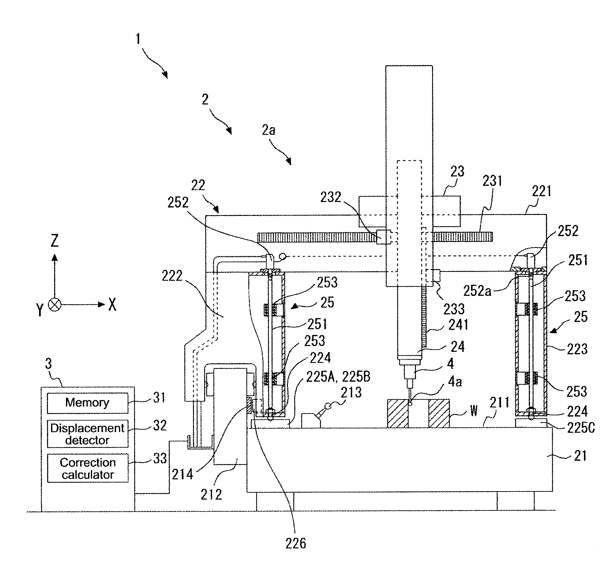
[0041]Hereafter, an embodiment of the present disclosure is described with reference to the drawings. Identical reference numerals are assigned to identical elements in each of the plurality of drawings, and duplicative descriptions are omitted where necessary.

[0042]FIG. 1 illustrates a schematic configuration of a coordinate measuring machine (an industrial machine) according to a first embodiment. In FIG. 1, a coordinate measuring machine 1 includes a measurer main body 2; a controller 3 executing drive control of the measurer main body 2, a process calculating three-dimensional coordinate values, and the like; and a probe 4 outputting to the controller 3 a signal indicating contact between a stylus head 4a and a work piece W (measured object) or a signal for an amount of displacement of the stylus head 4a due to the contact. The coordinate measuring machine 1 is a bridge displacement-type coordinate measuring machine. In addition, in some cases, the coordinate measuring machine 1...

second embodiment

[0067]Next, an industrial machine according to a second embodiment is described. Descriptions of aspects common to both the first and second embodiments may be omitted. Hereafter, a case is described where the industrial machine according to the second embodiment is a coordinate measuring machine; however, the industrial machine according to the second embodiment may also be a machine tool.

[0068]FIG. 4 illustrates a schematic configuration of the coordinate measuring machine (the industrial machine) according to the second embodiment. In FIG. 4, a coordinate measuring machine 10 includes a measurer main body 20; a controller 30 executing drive control of the measurer main body 20, a process calculating three-dimensional coordinate values, and the like; and a probe 4 outputting to the controller 30 a signal indicating contact between a stylus head and a work piece W (measured object, not shown in FIG. 4) or a signal for an amount of displacement of the stylus head due to the contact....

third embodiment

[0079]Next, a Z correction reference unit according to a third embodiment is described. Descriptions of aspects common to both the first and second embodiments may be omitted. FIG. 5 illustrates a schematic configuration of the Z correction reference unit according to the third embodiment. The Z correction reference unit 25 according to the third embodiment can be applied to either of the first and second embodiments. FIG. 5 illustrates an example in which the Z correction reference unit 25 according to the third embodiment is provided to the column 228; however, the Z correction reference unit 25 can also be provided to the column 222 or the supporter 223.

[0080]The Z correction reference unit 25 according to the third embodiment includes a temperature detection sensor 254 attached to the low thermal expansion shaft 251. The temperature detection sensor 254 detects a temperature of the low thermal expansion shaft 251 and outputs the detected temperature to one of the controller 3 an...


PUM

PropertyMeasurementUnit
temperatureaaaaaaaaaa
length Lsaaaaaaaaaa
temperatureaaaaaaaaaa

Abstract

An industrial machine includes a moving mechanism moving one of a probe and a tool relative to a work piece, using three displacement axes parallel to each of three orthogonal axis directions; a low thermal expansion member formed with a material having a smaller thermal expansion coefficient than a material forming a structural element of the moving mechanism; and an expansion / contraction measurer measuring, using the low thermal expansion member as a reference, an amount of expansion / contraction of the structural element in one of the three orthogonal axis directions, the expansion / contraction occurring due to a change in temperature.

Description

CROSS-REFERENCE TO RELATED APPLICATIONS[0001]The present application claims priority under 35 U.S.C. §119 of Japanese Application No. 2013-232675, filed on Nov. 11, 2013, the disclosure of which is expressly incorporated by reference herein in its entirety.BACKGROUND OF THE INVENTION[0002]1. Field of the Invention[0003]The present invention relates to an industrial machine used in measuring or processing a work piece, and to a method for measuring an amount of expansion / contraction of the industrial machine.[0004]2. Description of Related Art[0005]A coordinate measuring machine (industrial machine) used in measuring a work piece includes guidance corresponding to each of three mutually orthogonal axes; a movable body displacing along the guidance; a scale for measuring an amount of displacement of the movable body; and a probe detecting contact with the work piece (measured object). Such a coordinate measuring machine can obtain three-dimensional coordinate values of the probe from ...

Claims


Application Information

Patent Timeline
Patent Type & Authority Applications(United States)
IPC IPC(8): G01N25/16G01B11/14G01B7/14
CPCG01B7/14G01N25/16G01B11/14G01B5/0014G01B5/008G01B21/045
Inventor SAKAI, HISAYOSHI
Owner MITUTOYO CORP
Why Eureka
Try Eureka