Check patentability & draft patents in minutes with Patsnap Eureka AI!

Engaging mechanism

a technology of engendering mechanism and curved parts, which is applied in the direction of manufacturing tools, furniture parts, couplings, etc., can solve the problems of repeating engagement and disengagement cases damage to the curved parts, and achieve the effect of preventing the occurrence of local stress concentration and stably

Active Publication Date: 2015-05-14
ACCESS
View PDF7 Cites 2 Cited by
  • Summary
  • Abstract
  • Description
  • Claims
  • Application Information

AI Technical Summary

Benefits of technology

This patent describes an improved engaging mechanism that can withstand repeated engagement and disengagement without easily breaking down. The mechanism is designed to distribute stress over the entire engaged parts, which prevents damage to the engaging claw part. The engagement between the engaging member and the engaged member is achieved through curved engagement surfaces that provide a linear contact area. This allows for stable and resilient deformation of the engaging members and prevents local stress concentration on certain areas. Overall, this mechanism improves the durability and lifespan of the engaging members.

Problems solved by technology

However, there is still a danger that repetition of the engagement and disengagement cases damage to the curved part 126 of the hook-shaped piece 122.

Method used


Image

  • Engaging mechanism
  • Engaging mechanism
  • Engaging mechanism

Examples


Embodiment Construction

[0033]An engaging mechanism according to an embodiment of the invention will be described while referring to the accompanying drawings wherein like parts and components are designated by the same reference numerals to avoid duplicating description.

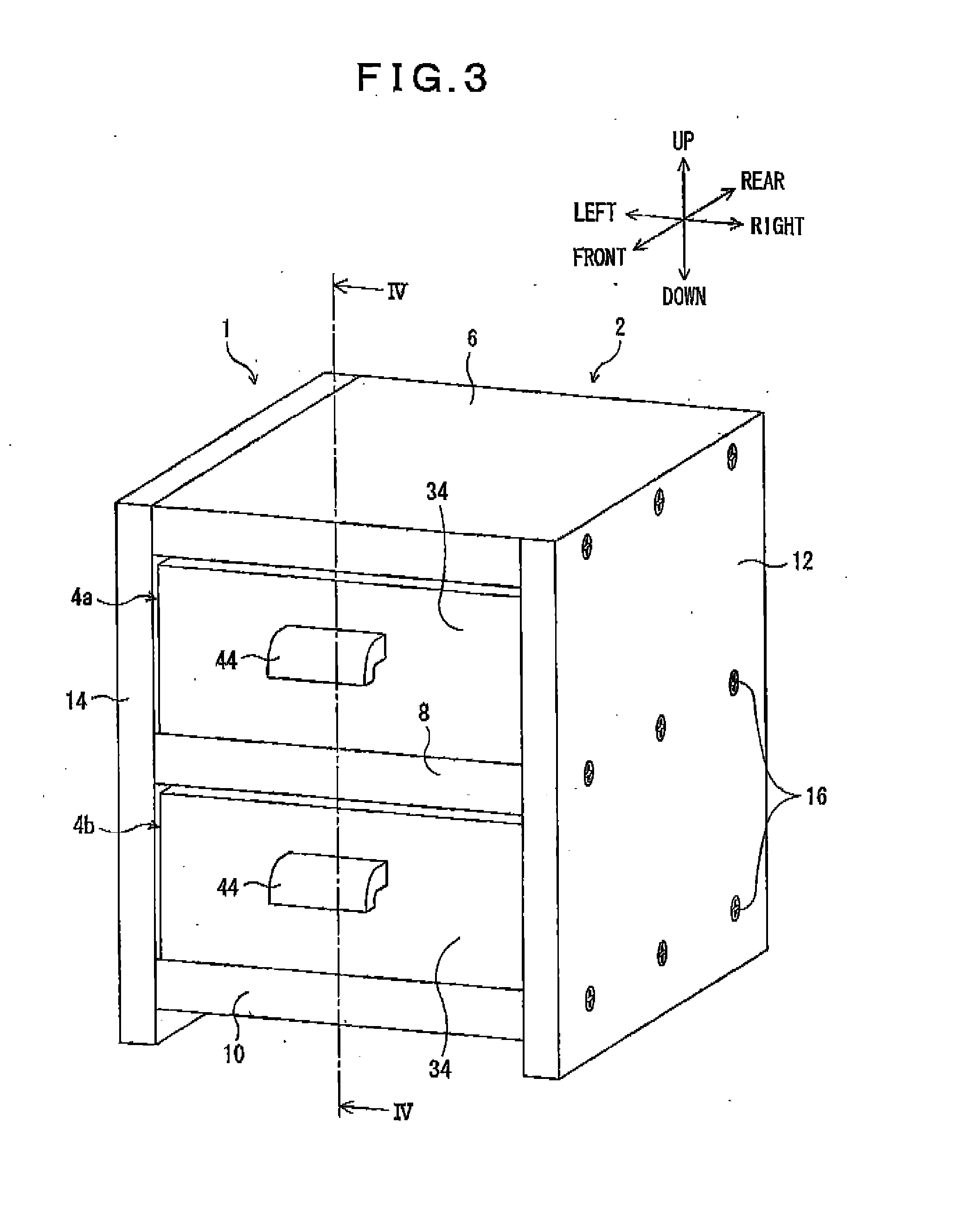
[0034]Before describing the engaging mechanism according to the embodiment, a storage box 1 utilizing the engaging mechanism will be described with reference to FIGS. 3 and 4. The storage box 1 has a box main body 2 and a pair of drawers 4a and 4b mounted one above the other in the box main body 2. The box main body 2 has an upper wall 6, a middle wall 8, a bottom wall 10, and a pair of side walls 12 and 14. The upper wall 6, the middle wall 8, and the bottom wall 10 are arranged in this order from the above to the bottom, and are disposed between and fixed to the pair of side walls 12 and 14 by, for example, fixing screws 16 (only those fixed to the right-side plate 12 are shown in FIG. 3).

[0035]The upper wall 6, the middle wall 8, and th...


PUM


Abstract

An engaging mechanism includes an engaging member and an engaged member freely detachably engageable with the engaging member. The engaging member includes an engaging main part and an engaging claw part formed on the engaging main part, both resiliently deformable. The engaging claw part has an inwardly curved engaging surface defined by a first curvature continuous curve. The engaged member includes an engaged part engageable with the engaging claw part and having an outwardly curved engaged surface defined by a second curvature continuous curve. The engaging surface and the engaged surface contact each other at a linear contact area at a time from when the engaging claw part and the engaged part are in engagement with each other through to when the engaging claw part is disengaged from the engaged part. A curvature of the engaging surface at the linear contact area is smaller than a curvature of the engaged surface at the linear contact area.

Description

BACKGROUND[0001]1. Technical Field[0002]The present invention relates to an engaging mechanism for freely detachably engaging two members with each other.[0003]2. Related Art[0004]An engaging mechanism is used for freely detachably engaging two members with each other. FIG. 1 shows an example of widely-used conventional engaging mechanisms. The engaging mechanism shown in FIG. 1 includes an engaging member 102 provided to a first member and an engaged member 104 provided to a second member. The engaging member 102 has an engaging main part 106 and an engaging claw part 108 formed on the engaging main part 106. The engaged member 104 is formed with an engaged part 110 that the engaging claw part 108 engages. The engaging claw part 108 has a planar engaging surface 112 that extends perpendicular to the engaging main part 106. Also, the engaged part 110 has a planar engaged surface 114 that extends parallel to and confronts the engaging surface 112.[0005]The engaging member 102 is move...

Claims


Application Information

Patent Timeline
Patent Type & Authority Applications(United States)
IPC IPC(8): F16B17/00
CPCF16B17/00E05B65/00F16B21/071F16B21/088A47B88/40E05B65/0014
Inventor KAMADA, KATSUZO
Owner ACCESS
Features
  • R&D
  • Intellectual Property
  • Life Sciences
  • Materials
  • Tech Scout
  • Unparalleled Data Quality
  • Higher Quality Content
  • 60% Fewer Hallucinations
Learn More