Plunger Pump, Plunger, and Method of Manufacturing Plunger Pump

a technology of plunger pump and plunger, which is applied in the direction of positive displacement liquid engine, piston pump, application, etc., can solve the problems of hollow plungers deflecting diametrically under loads, large diameter and/or longer stroke plungers with solid construction are often unwieldy to handle during routine maintenance operations, and the gap clearance may be small and have a detrimental effect on the life of packing, etc., to achieve the effect of improving the stiffness of the plunger and improving the stiffness of the plung

Inactive Publication Date: 2015-05-14
NAT OILWELL VARCO LP
View PDF13 Cites 69 Cited by
  • Summary
  • Abstract
  • Description
  • Claims
  • Application Information

AI Technical Summary

Benefits of technology

[0010]The subject matter disclosed herein relates to improvements in a plunger pump. In one illustrative embodiment, a plunger pump comprises a pump fluid end having a fluid chamber and a suction bore, discharge bore, and plunger bore in communication with the fluid chamber. A plunger is arranged to reciprocate into and out of the fluid chamber through the plunger bore. The plunger has a plunger body with an inner cavity and an insert disposed in the inner cavity to increase the stiffness of the plunger. A crank mechanism is coupled to the plunger and operable to reciprocate the plunger.

Problems solved by technology

However, slight increases in gap clearance may have a detrimental effect on the life of the packing due primarily to accelerated packing material extrusion.
However, larger diameter and / or longer stroke plungers with solid construction are often unwieldy to handle during routine maintenance operations.
Hollow plungers have been proposed, but these hollow plungers tend to deflect diametrically under loads.
This annular gap allows deformation of the connecting rod bearing surface during high load conditions, which can create uneven loading and premature bearing failure, such as galling.
However, the intersection of these two bores creates a surface discontinuity, significantly increasing stresses within these highly localized areas.
These surfaces normally fail due to fatigue as they are also exposed to cyclical loadings.

Method used


Image

  • Plunger Pump, Plunger, and Method of Manufacturing Plunger Pump
  • Plunger Pump, Plunger, and Method of Manufacturing Plunger Pump
  • Plunger Pump, Plunger, and Method of Manufacturing Plunger Pump

Examples


Embodiment Construction

[0023]In the following detailed description, numerous specific details may be set forth in order to provide a thorough understanding of the disclosed embodiments. However, it is to be understood that other embodiments of the invention may be practiced without incorporating some or all of the specific details that are a part of these disclosed embodiments. In other instances, well-known features or processes may not be described in detail in the disclosed embodiments so as not to unnecessarily obscure the disclosure. In addition, like or identical reference numerals may be used to identify common or similar elements between the embodiments.

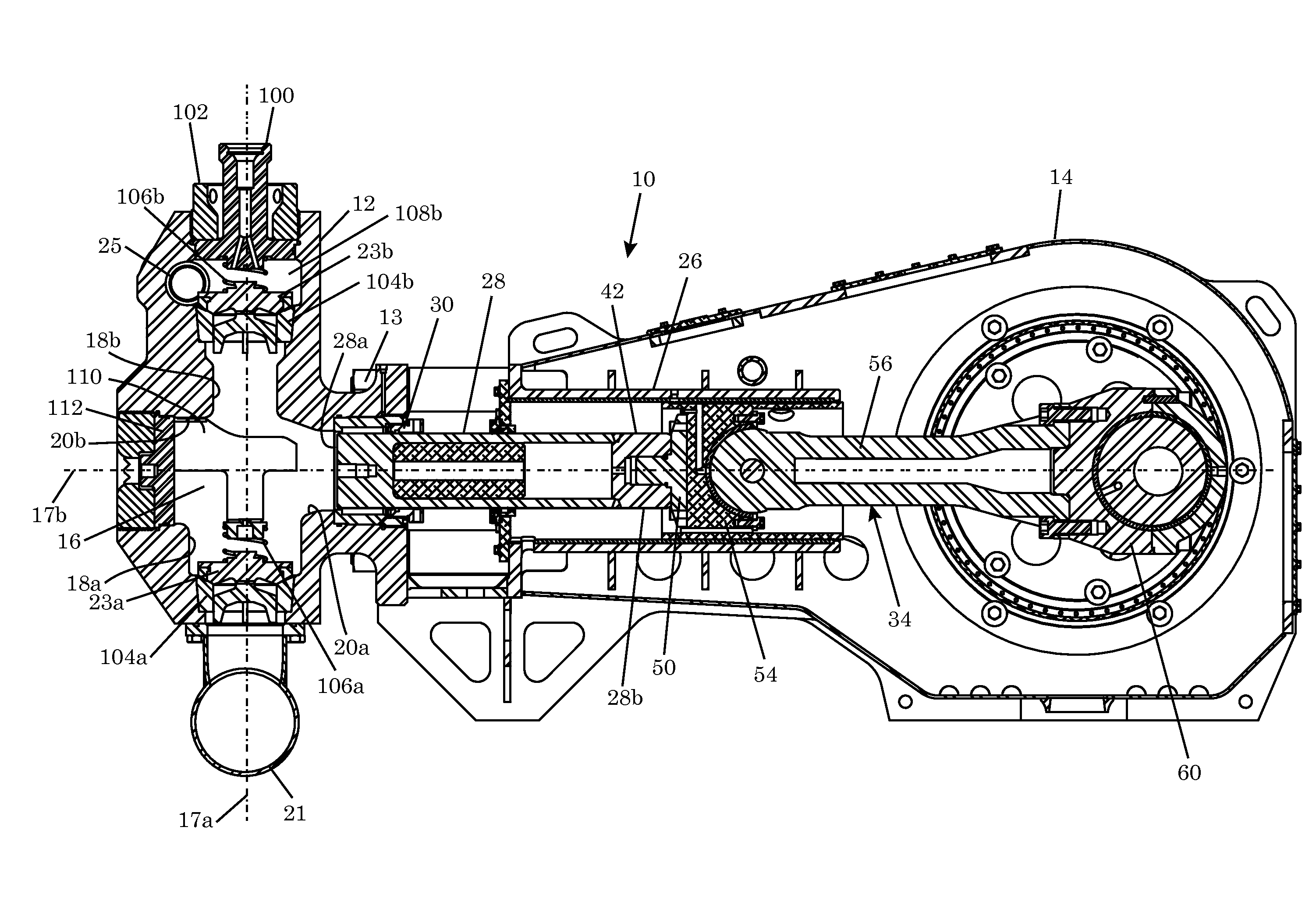
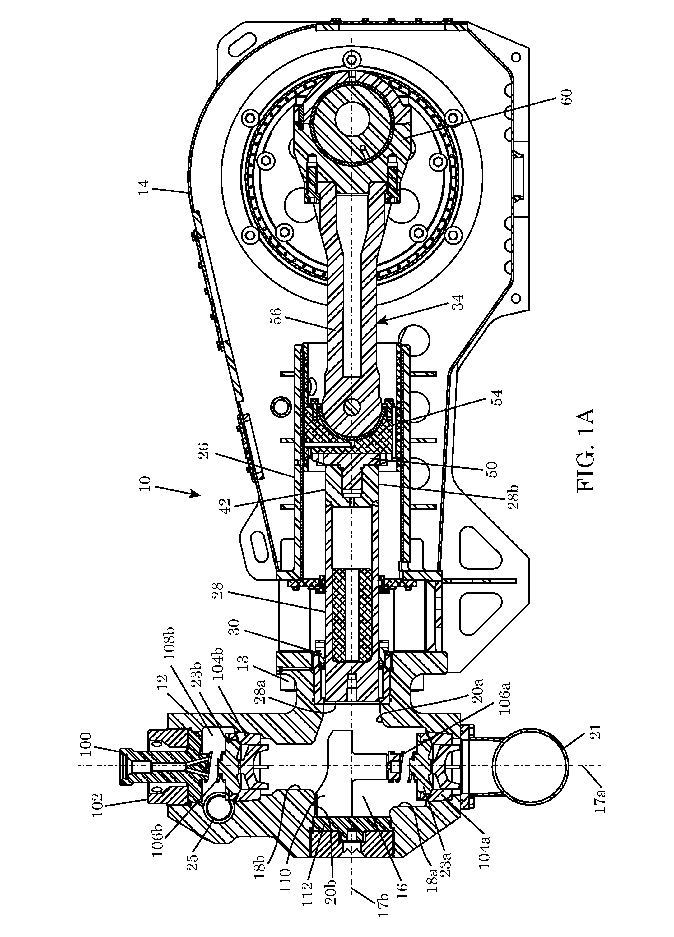
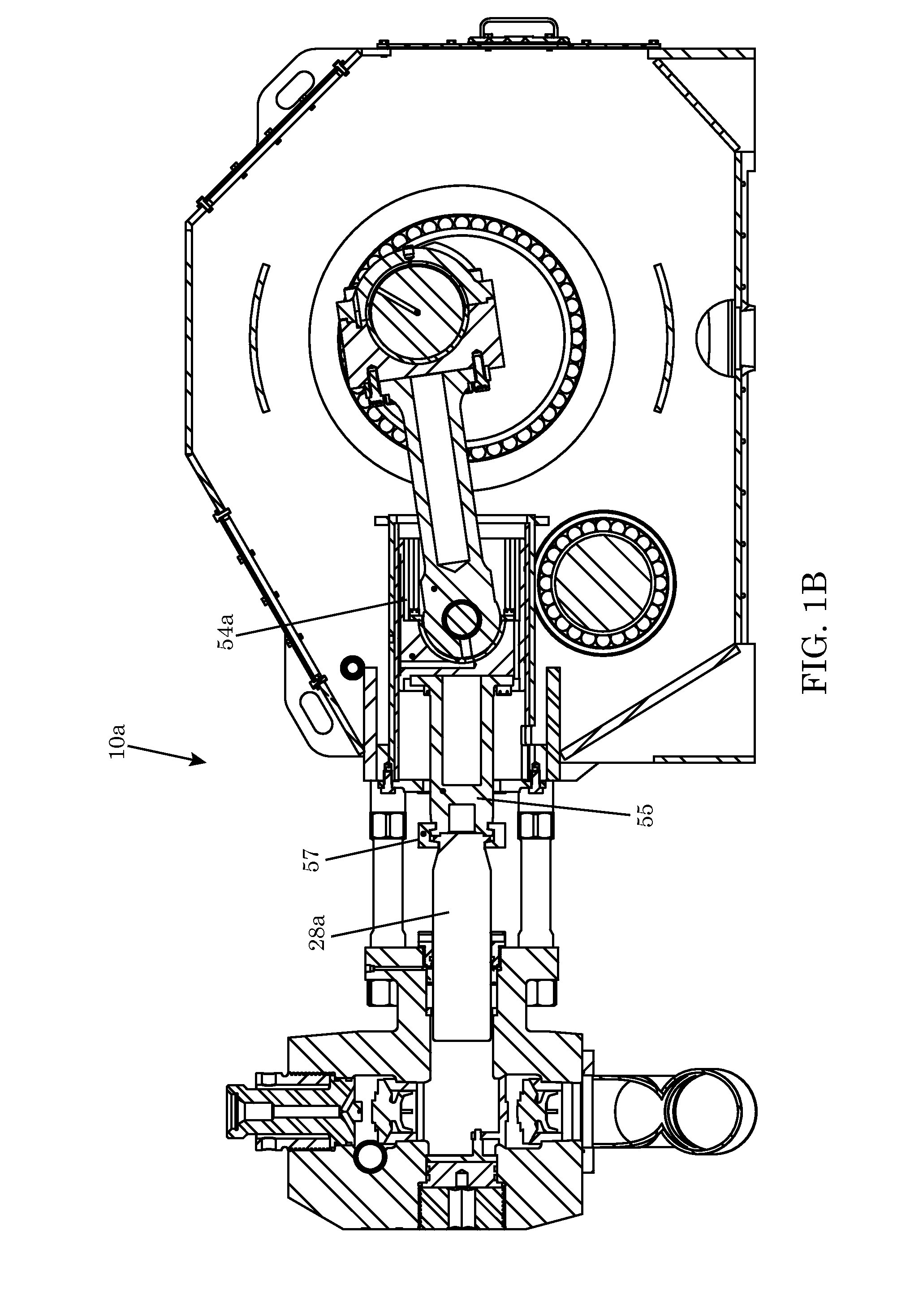
[0024]FIG. 1A is an illustrative embodiment of a plunger pump 10 having a pump fluid end 12 coupled to a pump power end 14 via stay rods 13. The pump fluid end 12 includes a fluid chamber 16. The pump fluid end 12 further includes a suction bore 18a, a discharge bore 18b, a plunger bore 20a, and an access bore 20b, all of which intersect with the f...


PUM

PropertyMeasurementUnit
localized stress concentrationsaaaaaaaaaa
stiffnessaaaaaaaaaa
volumeaaaaaaaaaa

Abstract

A plunger pump includes a pump fluid end having a fluid chamber and a suction bore, discharge bore, and plunger bore in communication with the fluid chamber. A plunger is arranged to reciprocate into and out of the fluid chamber through the plunger bore. The plunger has a plunger body with an inner cavity and an insert disposed in the inner cavity such that the combined stiffness of the insert and plunger body is greater than the stiffness of the plunger body. A crank mechanism is coupled to the plunger and operable to reciprocate the plunger.

Description

CROSS-REFERENCE TO RELATED APPLICATIONS[0001]Not applicable.STATEMENT REGARDING FEDERALLY SPONSORED RESEARCH OR DEVELOPMENT[0002]Not applicable.FIELD[0003]The field relates to construction of high pressure plunger pumps.BACKGROUND[0004]Well service pumps are used in the oil and gas industry to pump fluids down a well for various purposes. One common use of well service pumps is in hydraulic fracturing of formations. The pump can be used to pump a high pressure fluid containing solids into the well, where the high pressure fluid will expand fractures in the formation or fracture the formation, leaving larger fluid passages through which formation fluids can flow into the well. The solids in the fluid will remain in the larger fluid passages to prop the fluid passages open, thereby increasing well production.[0005]Well service pumps are commonly plunger pumps, which are a type of reciprocating positive displacement pumps. In these pumps, a plunger reciprocates axially in a fluid end, ...

Claims


Application Information

Patent Timeline
Patent Type & Authority Applications(United States)
IPC IPC(8): F04B53/14
CPCF04B53/14F04B47/02F04B47/12F04B53/16F04B53/162F16J1/16F16J1/18Y10T29/494
Inventor WHALEY, JASON NEALMOELLER, MANUELFOLK, HEATH GREGORY
Owner NAT OILWELL VARCO LP
Why Eureka
Try Eureka