
Safety cap assembly of power battery

a safety cap and power battery technology, applied in the direction of batteries, cell components, vent arrangements, etc., can solve the problems of serious safety accidents, power battery itself becomes a potential dangerous resource, and the structure in the above patent is complex, so as to improve the safety performance of the power battery and achieve high melting point, high electrical resistivity

Active Publication Date: 2015-05-14
DONGGUAN POWERAMP TECH LTD
View PDF2 Cites 15 Cited by
  • Summary
  • Abstract
  • Description
  • Claims
  • Application Information

AI Technical Summary

Benefits of technology

The present patent provides a safety cap assembly for power batteries that includes a coating with high electrical resistivity and melting point to control circuit resistance and protect safety reverse valve and short circuit protection conducting plate in case of external short circuits. The assembly also includes an additional resistance plate to further improve safety performance. The coating is simple to apply and practical to use, and the resistance plate is integrated into the insulating body. Overall, the assembly provides a simple and effective solution to improve safety performance of power batteries.

Problems solved by technology

The presence of the vent can improve the safety performance of the power battery to some extent, but if the energy gathered by the battery itself which is involved in the accident is not released, the power battery itself becomes a potential dangerous resource and there are still some safety problems left, if the power battery continues to be overcharged after involving the accident, more serious safety accidents will be caused.
For now, the structure in the above patent is complex, and the effect is not perfect when only the resistance plate is provided to control the current of the external short circuit.

Method used


Image

  • Safety cap assembly of power battery
  • Safety cap assembly of power battery
  • Safety cap assembly of power battery

Examples


Embodiment Construction

[0035]Hereinafter the present disclosure will be described in detail in combination with specific embodiments and drawings, but the present disclosure is not limited to these embodiments.

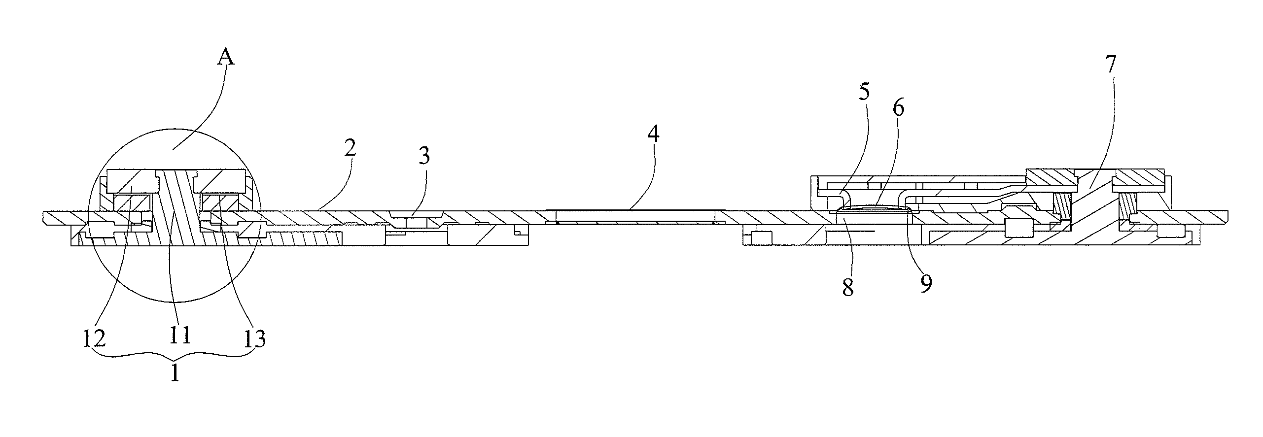
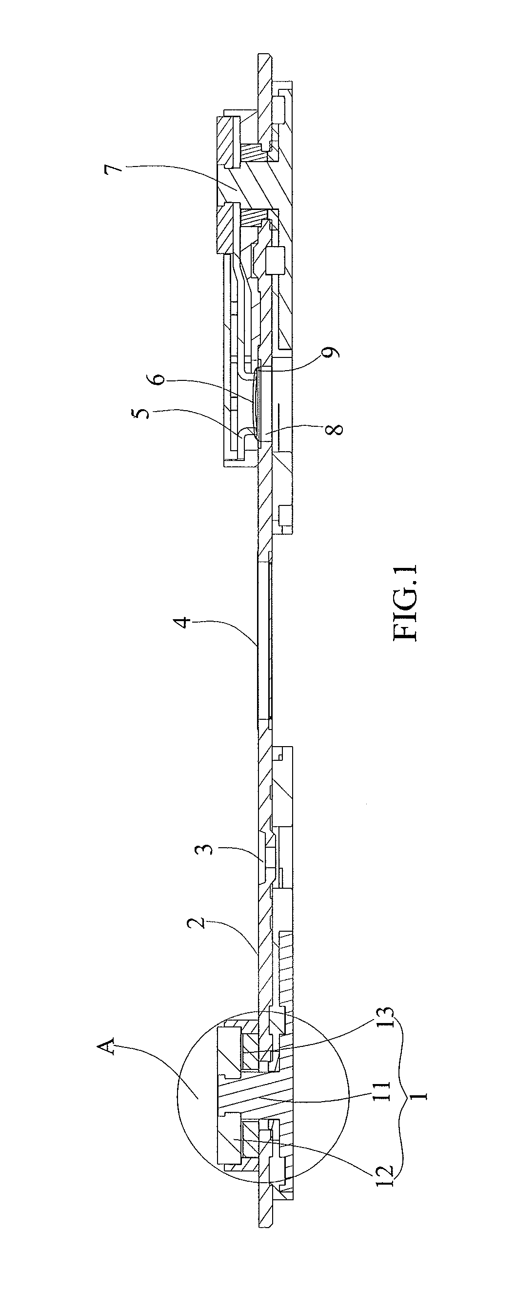
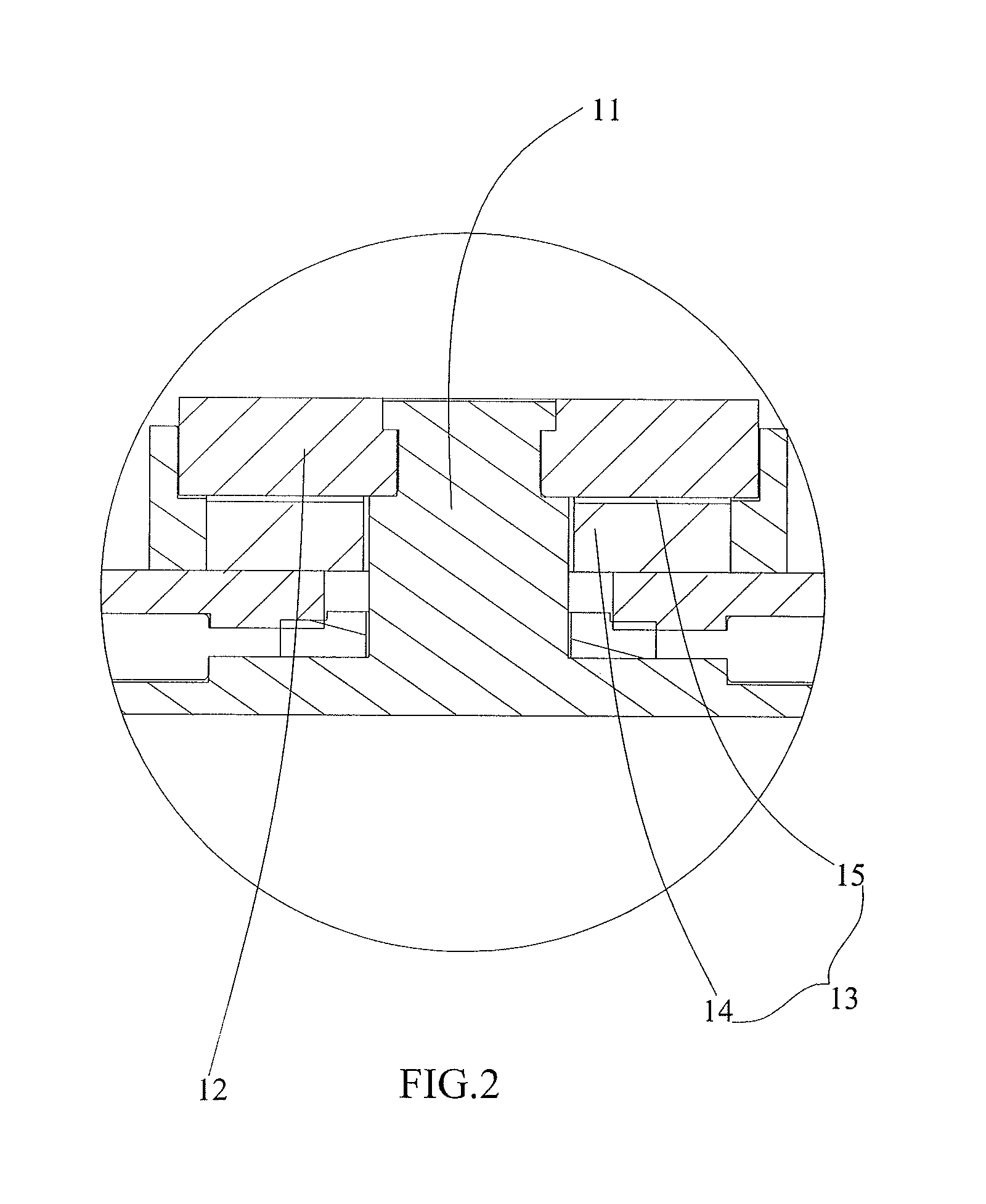
[0036]As shown in FIGS. 1-3, a safety cap assembly of power battery comprises a cap plate 2 and a first terminal unit 1, a second terminal unit 7, a vent 4, an electrolyte-injection hole 3 and a safety reverse valve 6 which are provided to the cap plate 2; the first terminal unit 1 is electrically connected to the cap plate 2; the second terminal unit 7 is insulated from and assembled to the cap plate 2; the safety reverse valve 6 is electrically connected to the cap plate 2; a short circuit protection conducting plate 5 is provided above the cap plate 2, the short circuit protection conducting plate 5 is electrically connected to the second terminal unit 7, the short circuit protection conducting plate 5 is positioned above the safety reverse valve 6; the safety reverse valve 6 and the short circui...


PUM

PropertyMeasurementUnit
thicknessaaaaaaaaaa
thicknessaaaaaaaaaa
depthaaaaaaaaaa

Abstract

A safety cap assembly of power battery comprises a cap plate and a first terminal unit, a second terminal unit, a vent, an electrolyte-injection hole and a safety reverse valve provided to the cap plate; the first terminal unit is electrically connected to the cap plate; the second terminal unit is insulated from and assembled to the cap plate; the safety reverse valve is electrically connected to the cap plate; a short circuit protection conducting plate is provided above the cap plate, is electrically connected to the second terminal unit, and is positioned above the safety reverse valve; the first terminal unit comprises a first terminal body, and a metal gasket and a resistance plate around the first terminal body, the resistance plate is provided below the metal gasket and comprises a substrate and a coating on a surface of the substrate.

Description

CROSS-REFERENCE TO RELATED APPLICATIONS[0001]The present application claims priority to Chinese patent application No.201320706489.5 filed on Nov. 11, 2013, which is incorporated herein by reference in its entirety.TECHNICAL FIELD OF THE PRESENT DISCLOSURE[0002]The present disclosure relates to the technical field of power batteries, and particularly relates to a safety cap assembly of power battery.BACKGROUND OF THE PRESENT DISCLOSURE[0003]With development of modern society and people's awareness of environmental protection, more and more equipments use a rechargeable secondary battery as a power source, such as mobile phones, laptops, electrical tools, electrical automobiles and the like, which provides a broad space for application and development of the rechargeable secondary battery.[0004]Generally, the electrical vehicles and energy storage stations need to use a high-capacity power battery as a power source. These power batteries should not only have high capacity, but should...

Claims


Application Information

Patent Timeline
Patent Type & Authority Applications(United States)
IPC IPC(8): H01M2/04H01M2/34H01M2/12H01M50/147H01M50/172H01M50/186H01M50/191H01M50/317H01M50/572H01M50/578H01M50/588
CPCH01M2/043H01M2/1223H01M2200/00H01M2220/20H01M2/34H01M2200/20H01M2220/10Y02E60/10H01M50/147H01M50/172H01M50/3425H01M50/572H01M50/186H01M50/191H01M50/317H01M50/30
Inventor HE, MENGJIANGCAI, RULAIDENG, PINGHUAWANG, PENGLI, QUANKUN
Owner DONGGUAN POWERAMP TECH LTD
Learn More