Intraocular shunt inserter

a technology of intraocular shunt and inserter, which is applied in the field of devices and methods of implanting an intraocular shunt into the eye, can solve the problem of unable to recover damaged visual field

Active Publication Date: 2015-05-14
AQUESYS INC
View PDF8 Cites 69 Cited by
  • Summary
  • Abstract
  • Description
  • Claims
  • Application Information

AI Technical Summary

Problems solved by technology

Untreated glaucoma leads to permanent damage of the optic nerve and resultant visual field loss, which can progress to blindness.
Once lost, this damaged visual field cannot be recovered.

Method used


Image

  • Intraocular shunt inserter
  • Intraocular shunt inserter
  • Intraocular shunt inserter

Examples


Embodiment Construction

[0154]In the following detailed description, numerous specific details are set forth to provide a full understanding of the subject technology. It should be understood that the subject technology may be practiced without some of these specific details. In other instances, well-known structures and techniques have not been shown in detail so as not to obscure the subject technology.

[0155]Further, while the present description sets forth specific details of various embodiments, it will be appreciated that the description is illustrative only and should not be construed in any way as limiting. Additionally, it is contemplated that although particular embodiments may be disclosed or shown in the context of ab interno procedures, such embodiments can be used in ab externo procedures. Furthermore, various applications of such embodiments and modifications thereto, which may occur to those who are skilled in the art, are also encompassed by the general concepts described herein.

[0156]Glauc...


PUM


Abstract

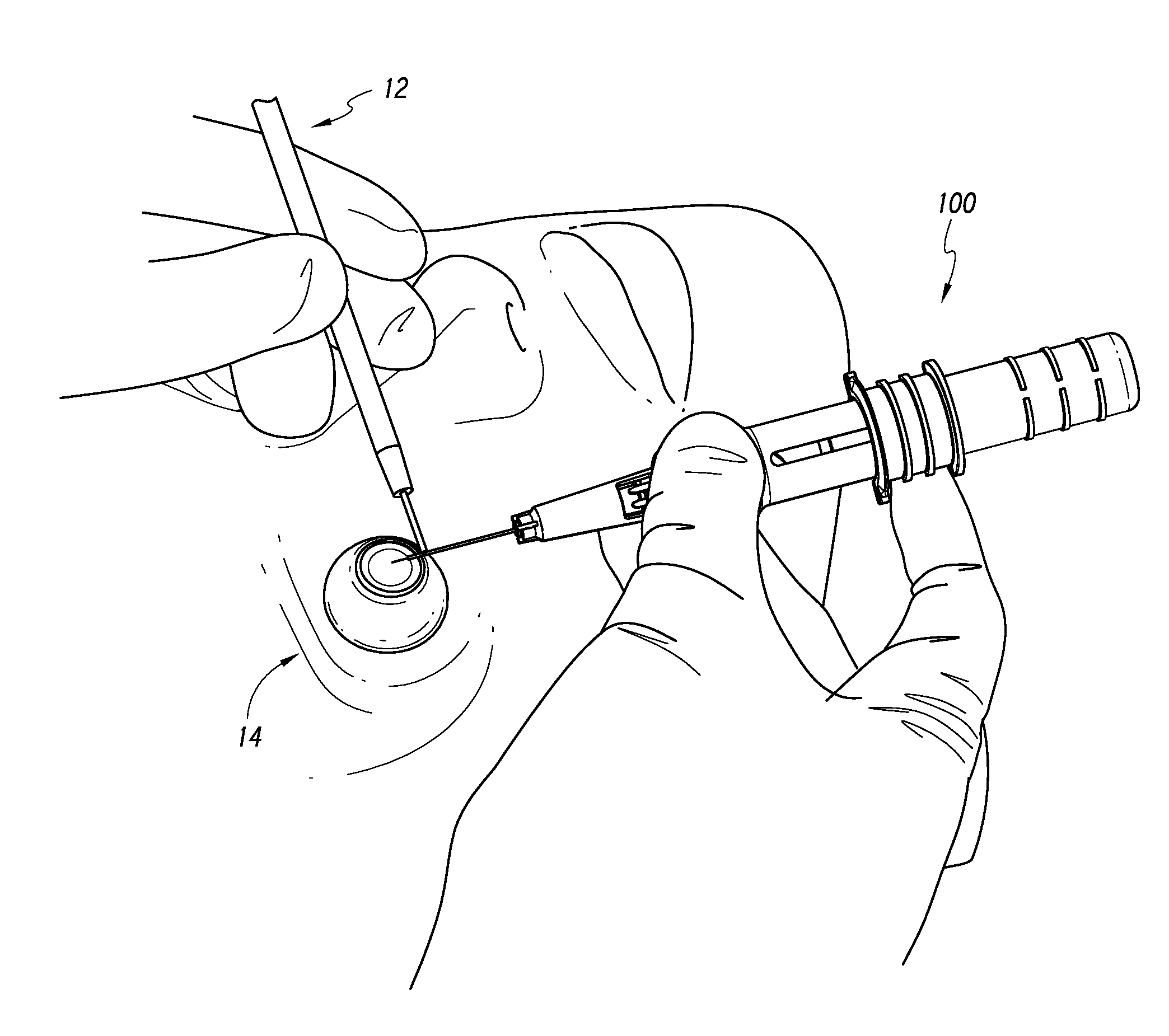
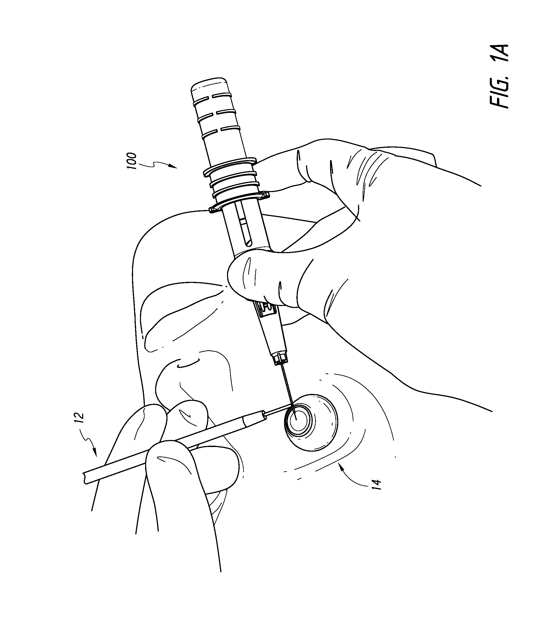
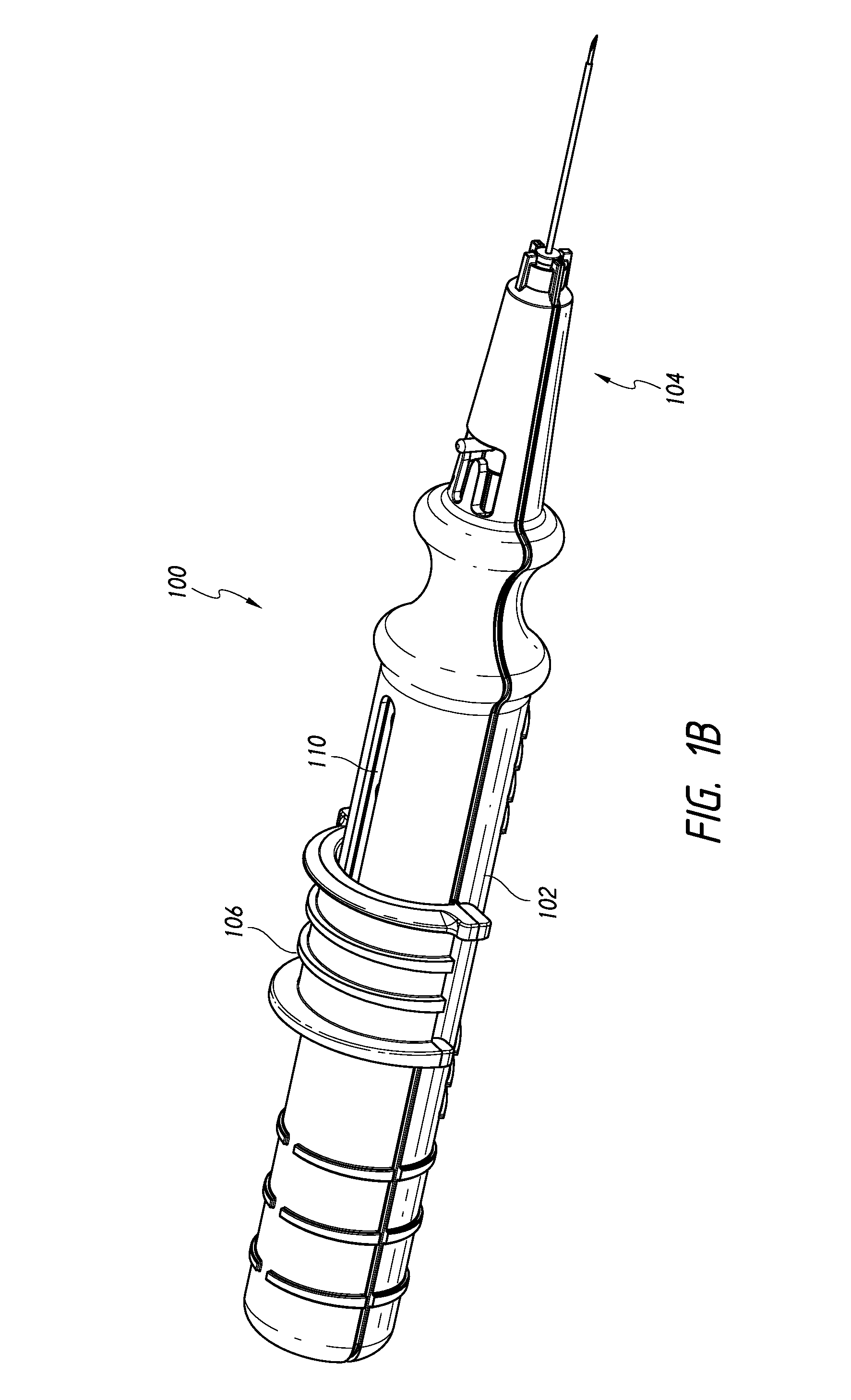
An inserter for treating glaucoma can comprise a housing, a needle, a plunger, a slider component, and a drive component. The drive component is disposed within a cavity of the housing and rotatable within the cavity to result in movement along a longitudinal axis of the inserter to the needle and the plunger upon rotation of the drive component. The slider component is coupled to the housing and slidable along an elongate groove of the drive component such that movement of the slider component along the axis rotates the drive component within the housing.

Description

CROSS-REFERENCE TO RELATED APPLICATIONS[0001]This application claims the benefit of U.S. Provisional Application No. 61 / 904,429, filed Nov. 14, 2013, the entirety of which is incorporated herein by reference.BACKGROUND[0002]1. Field of the Inventions[0003]The present disclosure generally relates to devices and methods of implanting an intraocular shunt into an eye.[0004]2. Description of the Related Art[0005]Glaucoma is a disease in which the optic nerve is damaged, leading to progressive, irreversible loss of vision. It is typically associated with increased pressure of the fluid (i.e., aqueous humor) in the eye. Untreated glaucoma leads to permanent damage of the optic nerve and resultant visual field loss, which can progress to blindness. Once lost, this damaged visual field cannot be recovered. Glaucoma is the second leading cause of blindness in the world, affecting 1 in 200 people under the age of fifty, and 1 in 10 over the age of eighty for a total of approximately 70 millio...

Claims


Application Information

Patent Timeline
Patent Type & Authority Applications(United States)
IPC IPC(8): A61F9/007A61M5/315A61M5/32
CPCA61F9/00781A61M5/3158A61M5/3286A61F9/0017A61F9/007A61F9/0008A61M27/002A61B90/02A61M2210/0612
Inventor HORVATH, CHRISTOPHERROMODA, LASZLO O.AHMED, IQBAL K.HAMSTROM, BRIAN SCOTTJUNG, WESLEY ANNEVERA, VANESSA I.BACHE, RONALD D.
Owner AQUESYS INC
Why Eureka
Try Eureka