Tank Venting Filter

a technology of tank venting and filter elements, which is applied in the direction of separation process, filtration separation, transportation and packaging, etc., can solve the problems of filter elements clogging relatively quickly with dust, dirt, water, etc., and achieve the effect of long residence time of air upstream, low air inflow rate, and increased sedimentation in the interior

Active Publication Date: 2015-05-21
MANN HUMMEL GMBH
View PDF10 Cites 0 Cited by
  • Summary
  • Abstract
  • Description
  • Claims
  • Application Information

AI Technical Summary

Benefits of technology

[0016]The air inlet may have several circumferentially positioned inflow openings. The inflow openings are preferably separated only by narrow webs. The total width of all webs in the circumferential direction can be less than 50% of the total width of all inflow openings in the circumferential direction. Preferably, the total width of all webs in the circumferential direction is less than 40%, particularly preferred less than 30%, of the total width of all inflow openings in the circumferential direction. As a result of the narrow webs, wide inflow openings are produced. Due to the wide inflow openings, a low inflow rate of the air into the air inlet can be achieved. Due to the low inflow rate, a long residence time of the air upstream of the filter element can be achieved. The quantity of the dust, dirt, and water which is sucked in with the air and sedimented in the interior can therefore be increased.
[0017]The air outlet is preferably embodied centrally on the topside of the filter. In this way, the tank venting filter can be used as an inline filter in a simple way.

Problems solved by technology

The filters known from the prior art have the disadvantage that the filter elements in the filter clog relatively quickly with dust, dirt, or water.

Method used


Image

  • Tank Venting Filter
  • Tank Venting Filter
  • Tank Venting Filter

Examples


Embodiment Construction

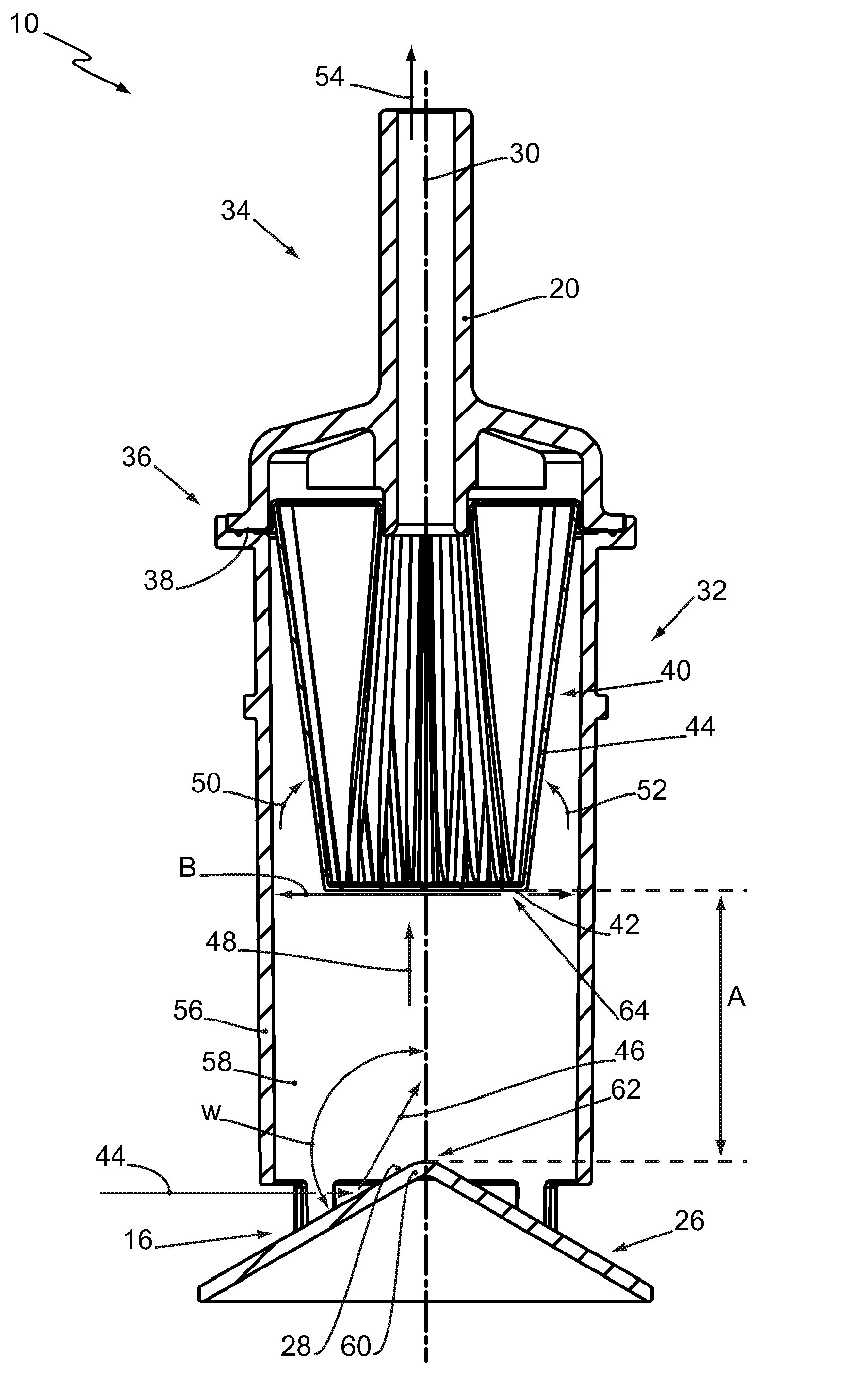
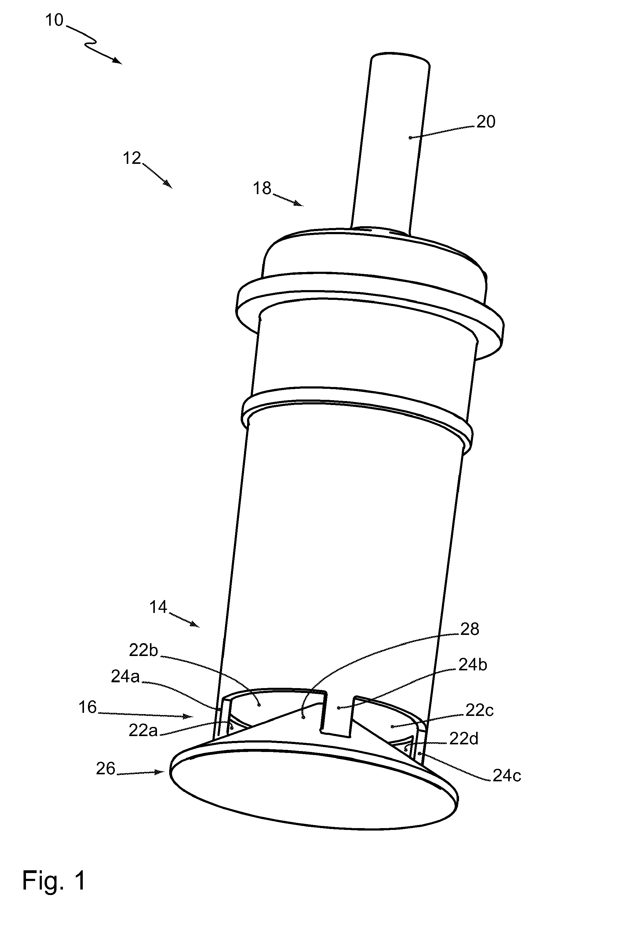
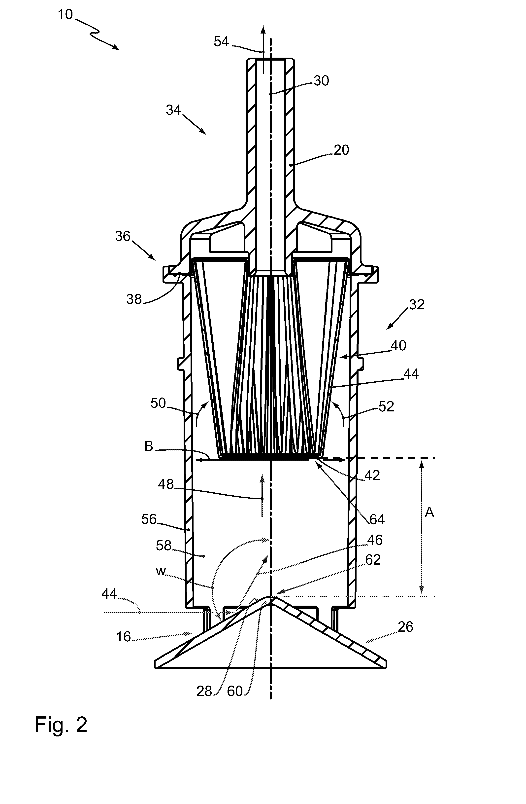
[0034]FIG. 1 shows a tank venting filter 10. The tank venting filter 10 serves for venting a tank (not illustrated) of a motor vehicle, for example, an automobile or a truck. When the tank venting filter 10 is provided for use in a truck, it typically has a height, i.e., an extension in longitudinal direction, of 10 cm to 20 cm.

[0035]The tank venting filter 10 comprises a housing 12. On the bottom side 14 of the housing 12, the housing 12 has a lateral air inlet 16. At the topside 18 of the housing 12, the housing 12 has an air outlet 20. The air outlet 20 is embodied centrally on the housing 12. The tank venting filter 10 is employed as an inline filter.

[0036]The air inlet 16 has four inflow openings 22a-22d. The inflow openings 22a-22d are arranged spaced apart from each other in circumferential direction of the housing. As shown in FIG. 1, the inflow openings 22a-22d are separated from each other by webs 24a-24c. The fourth web between the inflow openings 22a and 22d is embodied ...


PUM

PropertyMeasurementUnit
obtuse angleaaaaaaaaaa

Abstract

A tank venting filter is provided with a housing extending in a direction of a longitudinal filter axis and provided with a bottom side and a topside opposite the bottom side. A filter element is arranged in the housing. The housing has an air inlet at the bottom side and an air outlet at the topside. The air inlet is provided in the housing transverse to the longitudinal filter axis. The housing has a housing bottom at the bottom side, wherein the housing bottom closes off a filter interior of the housing in a downward direction and is positioned at a spacing from the filter element. The housing bottom has an inner side facing the filter interior. The inner side ends in the air inlet and is positioned at least sectionwise at an obtuse angle relative to the longitudinal filter axis.

Description

BACKGROUND OF THE INVENTION[0001]The invention concerns a tank venting filter comprising a housing that is extending in the direction of its longitudinal filter axis and comprising a filter element arranged in the housing.[0002]When from a tank, for example, a fuel tank or urea tank of a motor vehicle, a liquid is removed, the tank must be vented in order to avoid underpressure within the tank. The tank venting device enables sucking in ambient air into the tank upon removal of the liquid. When sucking in the ambient air, foreign matter, in particular dust, dirt or water, may however pass into the tank. Primarily when driving in rain, high water introduction may occur. In order for the foreign matter not to reach the tank, the tank venting device has in general a tank venting filter. Such a tank venting filter is the subject matter of the present invention.[0003]U.S. Pat. No. 3,546,853 A discloses a filter extending in longitudinal direction which has intake openings at its bottom s...

Claims


Application Information

Patent Timeline
Patent Type & Authority Applications(United States)
IPC IPC(8): B60K15/035
CPCB60K15/035B01D46/2403B01D46/0043B01D2279/35B60K2015/03236
Inventor HOLZWARTH, MARCELHEIM, MICHAELHORIYE, ADRIANO
Owner MANN HUMMEL GMBH
Why Eureka
Try Eureka