
Thermal power plant waste heat recovery device

A technology of waste heat recovery device and thermal power plant, applied in the direction of heat exchanger, heat exchange equipment, heat exchanger type, etc., can solve the problem of low heat exchange efficiency, and achieve high heat exchange efficiency, easy use and long heat exchange time. Effect

Pending Publication Date: 2019-02-01
GUODIAN LONGYUAN POWER TECH ENG
View PDF1 Cites 0 Cited by
  • Summary
  • Abstract
  • Description
  • Claims
  • Application Information

AI Technical Summary

Problems solved by technology

[0004] The invention provides a thermal power plant waste heat recovery device, which can solve the technical problem of low heat exchange efficiency in the prior art

Method used


Image

  • Thermal power plant waste heat recovery device
  • Thermal power plant waste heat recovery device

Examples


Embodiment Construction

[0024] The following will clearly and completely describe the technical solutions in the embodiments of the present invention with reference to the accompanying drawings in the embodiments of the present invention. Obviously, the described embodiments are only some, not all, embodiments of the present invention. Based on the embodiments of the present invention, all other embodiments obtained by persons of ordinary skill in the art without making creative efforts belong to the protection scope of the present invention.

[0025] In the description of the present invention, the terms "longitudinal", "transverse", "upper", "lower", "front", "rear", "left", "right", "vertical", "horizontal", " The orientations or positional relationships indicated by "top", "bottom", etc. are based on the orientations or positional relationships shown in the drawings, and are only for the convenience of describing the present invention and do not require that the present invention must be construct...


PUM


Abstract

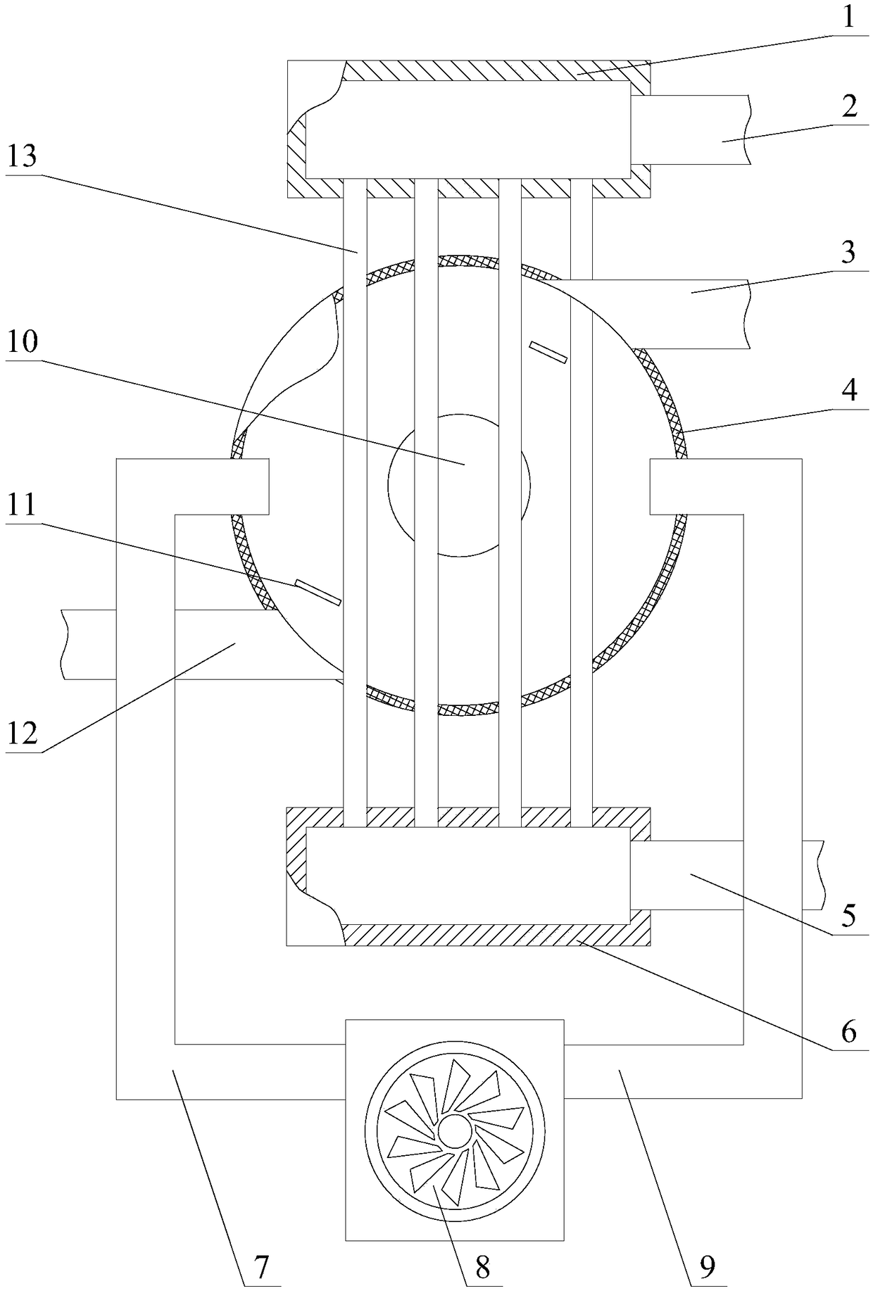
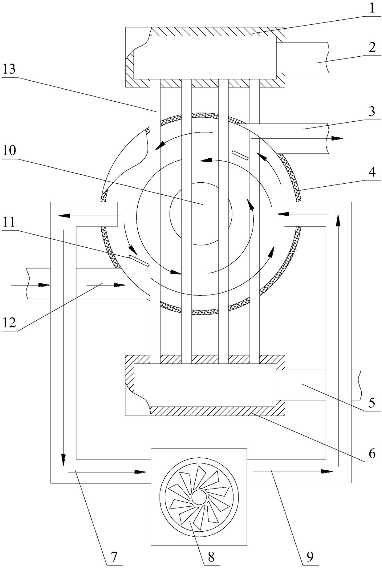
The invention belongs to the technical field of waste heat recovery and particularly relates to a thermal power plant waste heat recovery device comprising a heat exchange agent liquid inlet box and aheat exchange agent liquid outlet box which are connected through a heat exchange pipe. The thermal power plant waste heat recovery device further comprises a curved shell which communicates with a smoke inlet pipe and a smoke outlet pipe. Smoke enters the curved shell from the smoke inlet pipe, rotates in the curved shell and is discharged through the smoke outlet pipe. The curved shell is usedfor improving heat exchange efficiency of the smoke and a heat exchange agent in the heat exchange pipe, wherein the heat exchange pipe penetrates through the curved shell. Through the thermal power plant waste heat recovery device provided by the invention, the smoke can rotate in the curved shell, contact time of the smoke and the heat exchange pipe is long, the contact area is large, thus heatexchange efficiency of the smoke of the heat exchange agent can be improved, and the thermal power plant waste heat recovery device has the characteristic of high heat exchange efficiency.

Description

technical field [0001] The invention belongs to the technical field of waste heat recovery, in particular, the invention relates to a waste heat recovery device of a thermal power plant. Background technique [0002] Energy saving and consumption reduction is the foundation of the survival of enterprises. In recent years, due to the shortage of energy sources, energy saving and consumption reduction work has been paid more and more attention in enterprises. In electric heating plants, various advanced energy-saving furnace types are becoming more and more perfect, making fuel combustion more and more reasonable. However, as another breakthrough point for energy saving and consumption reduction in electric heating plants, the research and development of waste heat recovery devices for flue gas is not satisfactory. The current The waste heat recovery device still has the problem of low heat exchange efficiency, and the flue gas after heat exchange still contains high heat. ...

Claims


Application Information

Patent Timeline
Patent Type & Authority Applications(China)
IPC IPC(8): F28D21/00F28F9/22
CPCF28D21/0014F28F9/22
Inventor 董浩
Owner GUODIAN LONGYUAN POWER TECH ENG
Learn More