Liquid yield from fluid coking reactors

a technology of fluid coking reactor and liquid yield, which is applied in the direction of chemistry apparatus and processes, thermal non-catalytic cracking, chemical/physical processes, etc., can solve the problem of liquid refluxing to make more coke, and achieve the effect of reducing coke yield, long residence time, and improving liquid yield

Active Publication Date: 2020-07-07
SYNCRUDE CANADA LTD
View PDF5 Cites 0 Cited by
  • Summary
  • Abstract
  • Description
  • Claims
  • Application Information

AI Technical Summary

Benefits of technology

[0007]It was discovered by the present applicant that when the hydrocarbon feed is distributed on solids (coke particles) present in the annular region, the feed will be exposed to higher reactor severity, i.e., higher vapour residence time, as it will take time for the liquid to vapourize and the vapour to move to the core in order to exit the dense bed. Thus, product evolved in the annulus would have a relatively long residence time and suffer over-cracking, thereby making gas or causing liquid refluxing to make more coke.
[0008]Conventionally, hydrocarbon feed nozzles are positioned closer to the wall of the reactor than the center of the vessel. Thus, conventional feed nozzles are positioned in the annular region and not the core where there is a stronger up flow of well mixed solids. The present applicant has discovered that by having the nozzle tips of feed nozzles extending into the core region of the reactor there is improved steam and feed liquid distribution throughout the reactor region (i.e., in the annulus as well as the core) and therefore improved liquid yields (in particular, heavy gas oil or HGO) and reduced coke yields.
[0009]The present invention is directed towards modifying the length of the feed nozzles delivering the hydrocarbon feed into the reactor section of a fluidized coke reactor such that the majority of the hydrocarbon feed will react in the core region of the reactor section and that any hydrocarbon vapour that is produced in the annular region will be released into the core region. Therefore, the present invention reduces the residence time of vapour immediately flashed from the injected hydrocarbon feed, resulting in reduced secondary vapour phase cracking. Further, any vapour generated by cracking of the feed pitch molecules (material that boils above 524° C.) will be preferentially stripped. If the majority of the feed is placed in the core, there will be reduced by-passing of wet solids into the stripper and core of the reactor vessel, as the net flow of solids in the core is upwards. This results in additional solids residence time for wet particles, which would contribute to less liquid carry-under, hence, reduced fouling of stripper and cone internals.

Problems solved by technology

Thus, product evolved in the annulus would have a relatively long residence time and suffer over-cracking, thereby making gas or causing liquid refluxing to make more coke.

Method used


Image

  • Liquid yield from fluid coking reactors
  • Liquid yield from fluid coking reactors
  • Liquid yield from fluid coking reactors

Examples


example 1

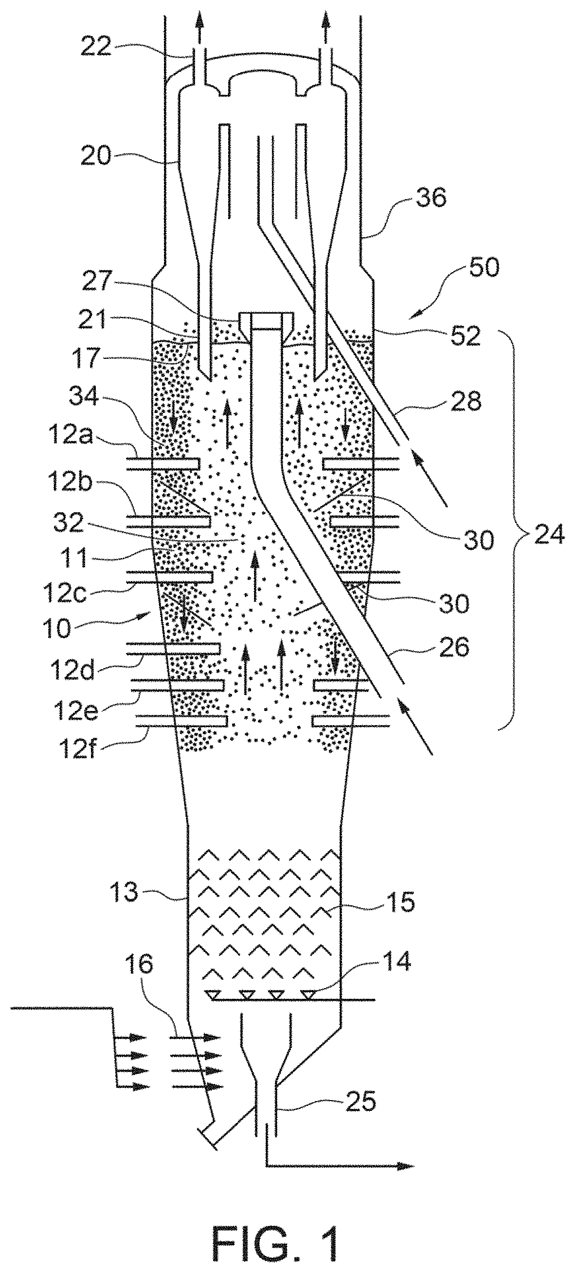
[0034]A 1 / 19th scaled commercial coker cold flow model was used to demonstrate that solids in a reactor generate a distinct core-annular flow structure. This was accomplished by inserting the feed nozzles (simulated by air jets) such that their maximum jet penetration reached the centerline (r=0) of the fluidized bed. The result was no measurable change in vapour residence time and significant increase in solids residence time in the reactor model. The slower moving solids suggest a more distinct core-annular flow structure. No change in the model vapour phase residence time is reasonable, since the vapour phase already rises quickly.

[0035]Experiments conducted with respect to feed-solids contact also supports injecting feed liquid into the core-annular flow structure. Liquid injection into a solids mixing regime representing the core region was vastly improved compared to the same injection done into a regime representing the annulus region. Surprisingly, the poor reaction performa...

example 2

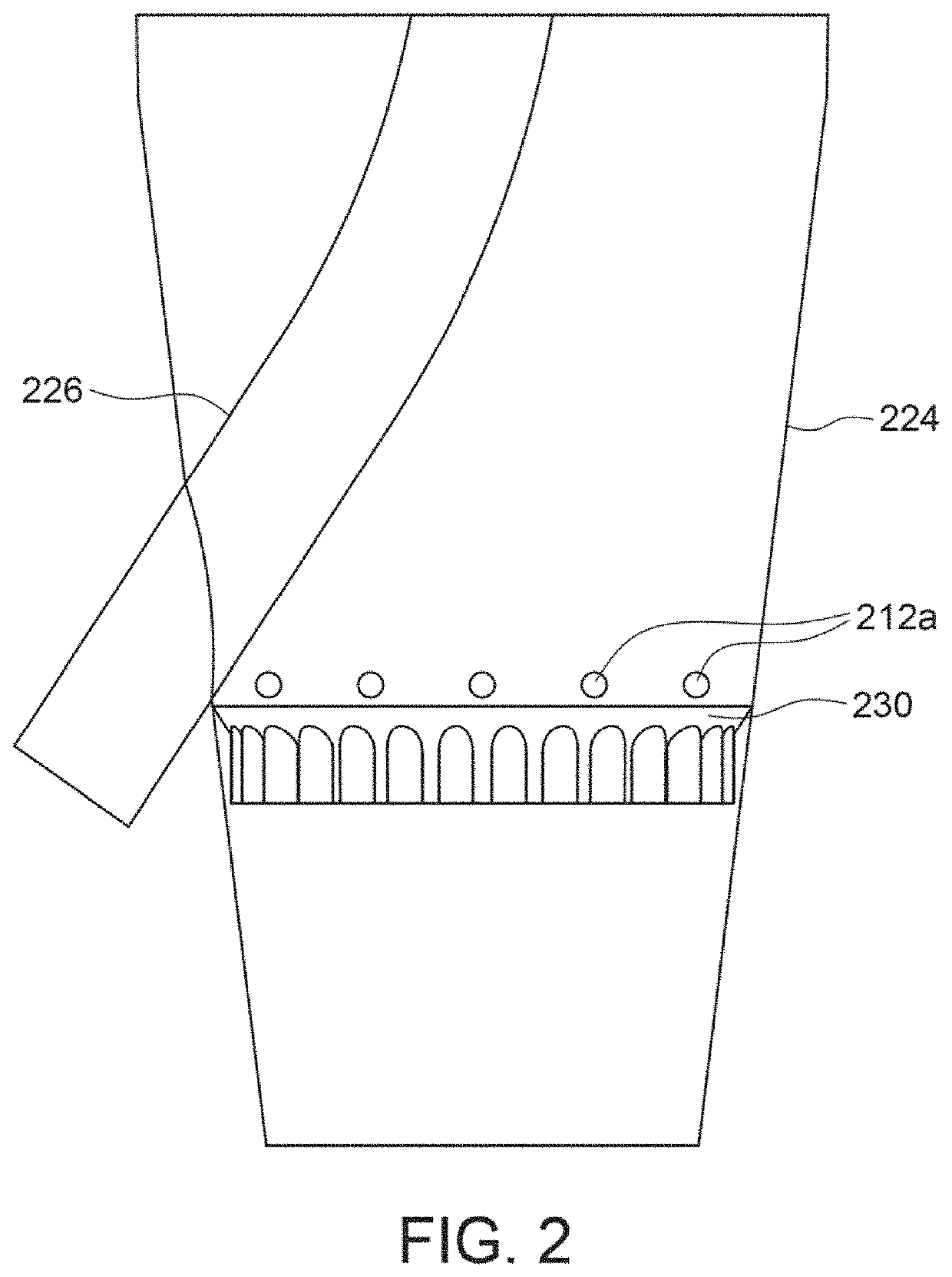
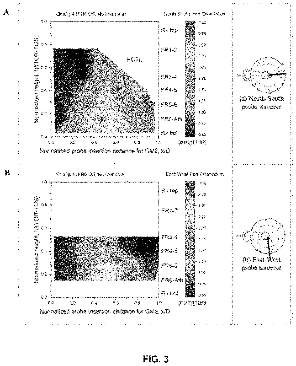
[0037]Experiments were performed using the 1 / 9th scaled commercial coker cold flow model and using helium as a steam tracer in the coker reactor section. Four different parameters were studied: Parameter 1 is where the nominal feed nozzles are positioned (i.e., extended) as currently used in commercial fluid cokers (the base case); Parameter 2 is where the nominal feed nozzles are extended to the core of the reactor; Parameter 3 is where the nominal feed nozzles are extended to the core of the reactor and one wall baffle is added; and Parameter 4 is where the nominal feed nozzles are extended to the core of the reactor and two wall baffles are added. As in applicant's commercial cokers, six (6) feed rings were used, each feed ring having a number of feed nozzles ranging from twelve (12) to eighteen (18).

[0038]Table 1 below compares the length of nozzles in the 1 / 9th scale commercial coker for the base case, i.e., the position of nozzle tips in commercial operations (Parameter 1), an...


PUM

PropertyMeasurementUnit
angleaaaaaaaaaa
angleaaaaaaaaaa
temperaturesaaaaaaaaaa

Abstract

The present invention is directed towards modifying the internals of the reactor section of a fluidized coke reactor such that the majority of the hydrocarbon feed will react in the core region of the reactor section and that any hydrocarbon vapour that is produced in the annular region will be released into the core region. Therefore, the present invention reduces the residence time of vapour immediately flashed from the injected hydrocarbon feed, resulting in reduced secondary vapour phase cracking.

Description

FIELD OF THE INVENTION[0001]This invention relates to a fluid coking apparatus and process for converting a heavy hydrocarbonaceous feedstock to liquid products.BACKGROUND OF THE INVENTION[0002]Fluidized bed coking (fluid coking) is a petroleum refining process in which heavy petroleum feeds, typically the non-distillable residue (resid) from fractionation or heavy oils are converted to lighter, more useful products by thermal decomposition (coking) at elevated reaction temperatures, typically about 480 to 590° C., (about 900 to 1100° F.) and in most cases from 500 to 550° C. (about 930 to 1020° F.). Heavy oils that may be processed by the fluid coking process include heavy atmospheric resids, vacuum resids, aromatic extracts, asphalts, and bitumen from oil sands.[0003]The process is carried out in a unit with a large reactor vessel containing hot coke particles that are maintained in the fluidized condition at the required reaction temperature with a fluidizing gas (e.g., steam) in...

Claims


Application Information

Patent Timeline
Patent Type & Authority Patents(United States)
IPC IPC(8): C10B55/10C10G9/00C10G9/32
CPCC10G9/32C10G9/005C10B55/10C10J2300/0943B01J6/008B01J8/004B01J8/1827B01J8/1872
Inventor WORMSBECKER, MICHAELMCMILLAN, JENNIFERMCKNIGHT, CRAIGWIENS, JASON
Owner SYNCRUDE CANADA LTD
Why Eureka
Try Eureka