
Systems and Methods For Cleaning A Membrane Separation System

a separation system and membrane technology, applied in membrane technology, membranes, chemistry apparatus and processes, etc., can solve the problems of reducing the efficiency of the membrane, consuming large amounts of clean water, and current cleaning methods that are time-consuming and expensiv

Inactive Publication Date: 2015-05-21
LUCAS KEVIN
View PDF9 Cites 0 Cited by
  • Summary
  • Abstract
  • Description
  • Claims
  • Application Information

AI Technical Summary

Benefits of technology

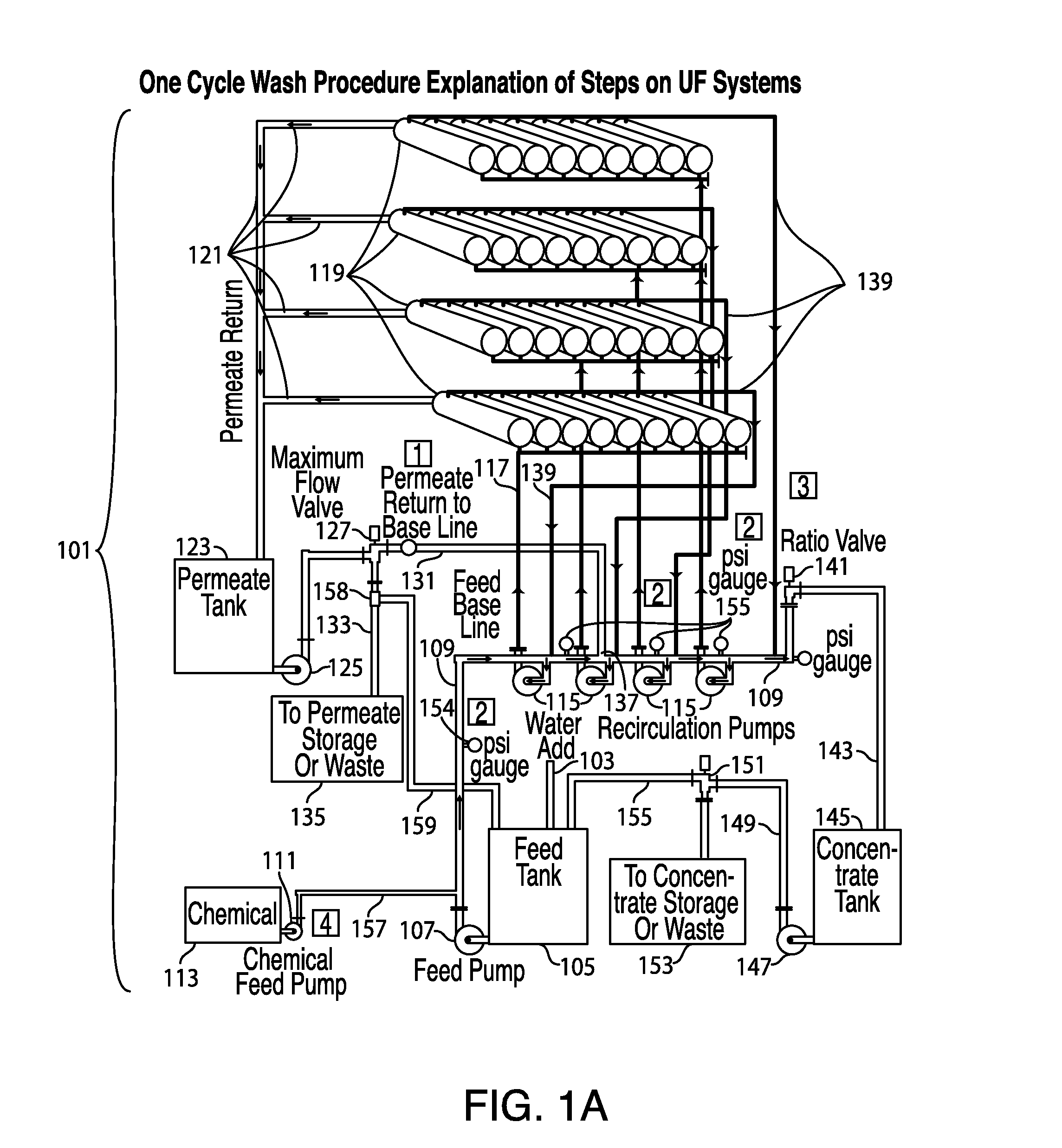
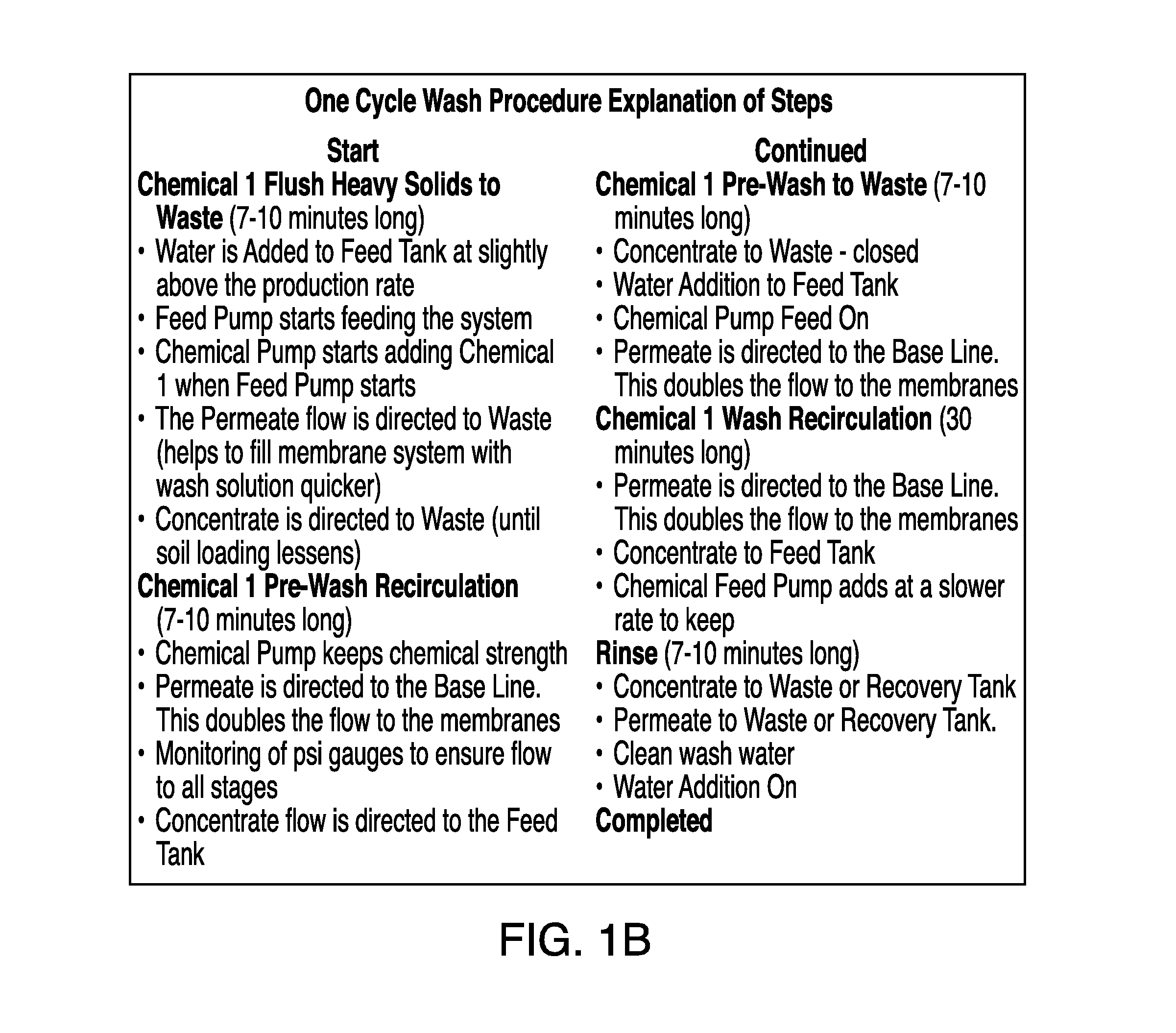
The patent describes a method for cleaning a membrane filtration system by using a cross-flow pressure to remove solid particulate from the membrane. The method involves maintaining a fluid pressure in the base line of the system to cause the membrane to be cleaned by fluid cross-flow. The cleaning process can be performed by flushing the system with fresh water and draining the concentrate and waste. The membrane filtration system can be a reverse osmosis or nanofiltration system. The technical effect of the patent is to provide a more effective and efficient method for cleaning membrane filtration systems.

Problems solved by technology

Over time, certain particles adhere to the membrane but do not pass through it, reducing the efficiency of the membrane.
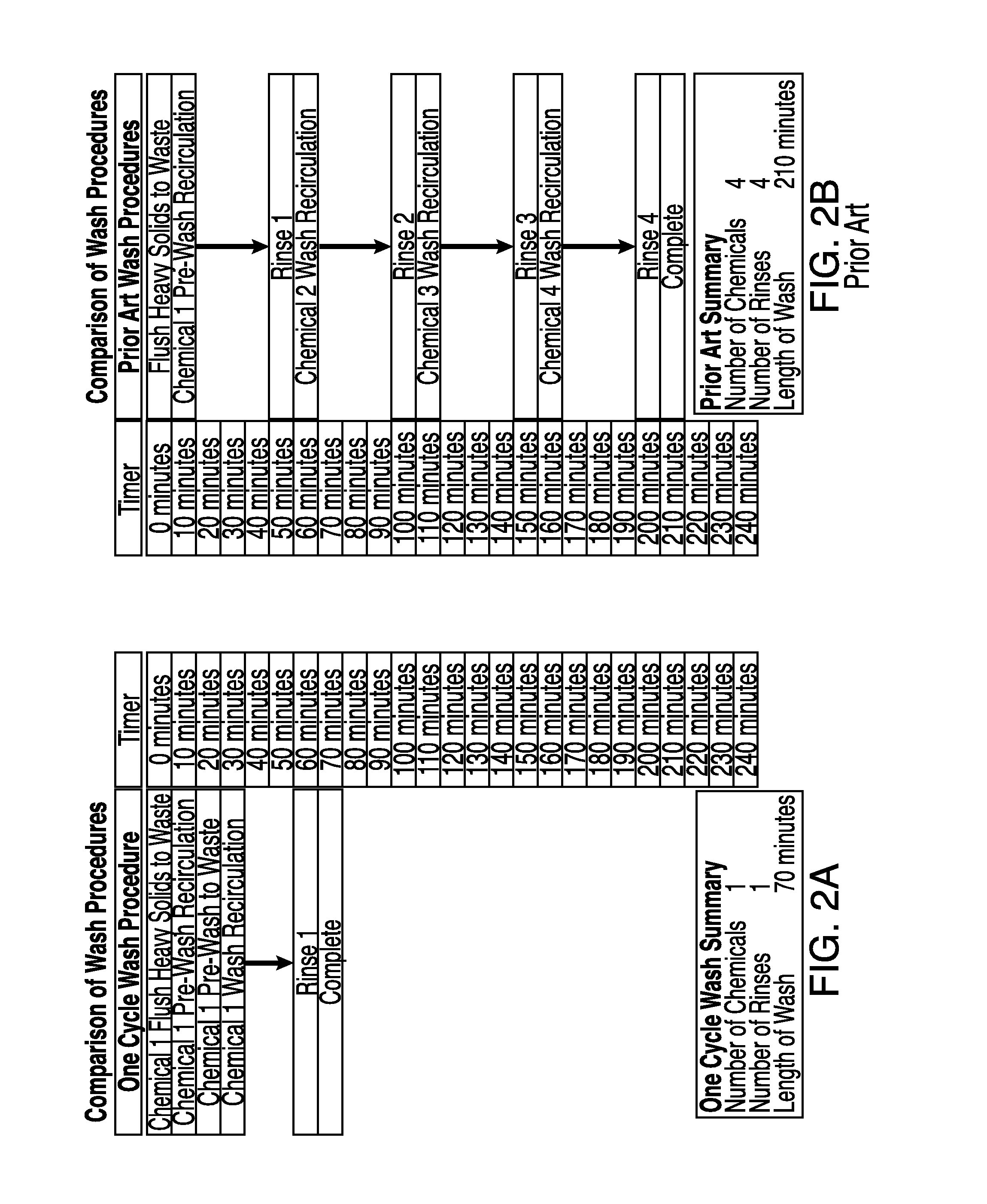
Current cleaning methods are time-consuming, expensive, and hard on the membranes, often involving the use of four different chemical washes and a rinse cycle after each such wash.
Large amounts of clean water must be consumed when rinsing and flushing the system.
Some of the cost efficiency gained in a membrane system by avoiding the energy needs of thermal separation is lost in the operational overhead of cleaning the systems.
However, high TMP reduces the cross-flow rate of wash solution across the membrane, thereby inhibiting removal of foulants and in many cases further packing them, such as by pushing lodged particulate further into the pores.
This wastes water, and the concentration is usually not determined by checking soil load levels.
This prolongs downtime and consumers more fresh water, driving up opportunity cost and operational cost.
Prior art methods also do not make efficient use of cleaning solution, requiring the use of multiple expensive and environmentally hazardous chemicals.
Prior art methods also use measurements of pressure taken at end-line as proxies for system-wide or nominal base line pressure, resulting in improperly configured systems that do not achieve preferred cross-flow rates for cleaning.

Method used


Image

  • Systems and Methods For Cleaning A Membrane Separation System
  • Systems and Methods For Cleaning A Membrane Separation System
  • Systems and Methods For Cleaning A Membrane Separation System

Examples


Embodiment Construction

)

[0039]The following detailed description and disclosure illustrates by way of example and not by way of limitation. This description will clearly enable one skilled in the art to make and use the disclosed systems and methods, and describes several embodiments, adaptations, variations, alternatives and uses of the disclosed systems and apparatus. As various changes could be made in the above constructions without departing from the scope of the disclosures, it is intended that all matter contained in the above description or shown in the accompanying drawings shall be interpreted as illustrative and not in a limiting sense.

[0040]Described herein, among other things, are methods for cleaning a membrane separation system wherein cross-flow of wash solution is used as the primary physical cleaning mechanism of a membrane, and the system is configured to maintain sufficient cross-flow by maintaining preferred pressure in supply lines supplying solution to the members. The described met...


PUM


Abstract

Systems and methods for cleaning a membrane filtration system using cross-flow geometry.

Description

CROSS REFERENCE TO RELATED APPLICATIONS[0001]This application claims benefit of U.S. Provisional Patent Application No. 61 / 901,920 filed Nov. 8, 2013, the entire disclosure of which is incorporated herein by reference.BACKGROUND[0002]1. Field of the Invention[0003]This disclosure is related to the field of membrane filtration, specifically to methods for cleaning such systems.[0004]2. Description of the Related Art[0005]This disclosure is related to the field of membrane filtration, specifically to methods for cleaning such systems.[0006]Many industrial setting membrane filtration systems separate gaseous or liquid streams, generally by removing certain solid particulates from them. Unlike chemical processes, such as distillation, sublimation, and crystallization, membrane separation generally operates without the application of heat, and thus requires less energy. Sometimes also known as “cold membrane technology,” these systems use physical rather than thermal processes, and are w...

Claims


Application Information

Patent Timeline
Patent Type & Authority Applications(United States)
IPC IPC(8): B01D65/02
CPCB01D65/02B01D2321/168B01D2321/08B01D2321/04B01D2315/10B01D2321/02
Inventor LUCAS, KEVIN
Owner LUCAS KEVIN
Learn More