Room heater

a technology for room heaters and heaters, applied in space heating and ventilation control systems, heating types, lighting and heating equipment, etc., can solve problems such as inability to mount the side of the room heater

Active Publication Date: 2015-05-21
RINNAI CORP
View PDF0 Cites 2 Cited by
  • Summary
  • Abstract
  • Description
  • Claims
  • Application Information

AI Technical Summary

Benefits of technology

The present invention provides a room heater that can control temperature without making the user uncomfortable. The invention prevents the temperature control at a low level that can make the user uncomfortable by updating the set temperature only when the room air temperature has exceeded the minimum lower reference temperature. This results in a more comfortable user experience.

Problems solved by technology

Further, since it is impossible on the side of the room heater to recognize the first reference temperature and the second reference temperature.

Method used


Image

  • Room heater
  • Room heater
  • Room heater

Examples


Embodiment Construction

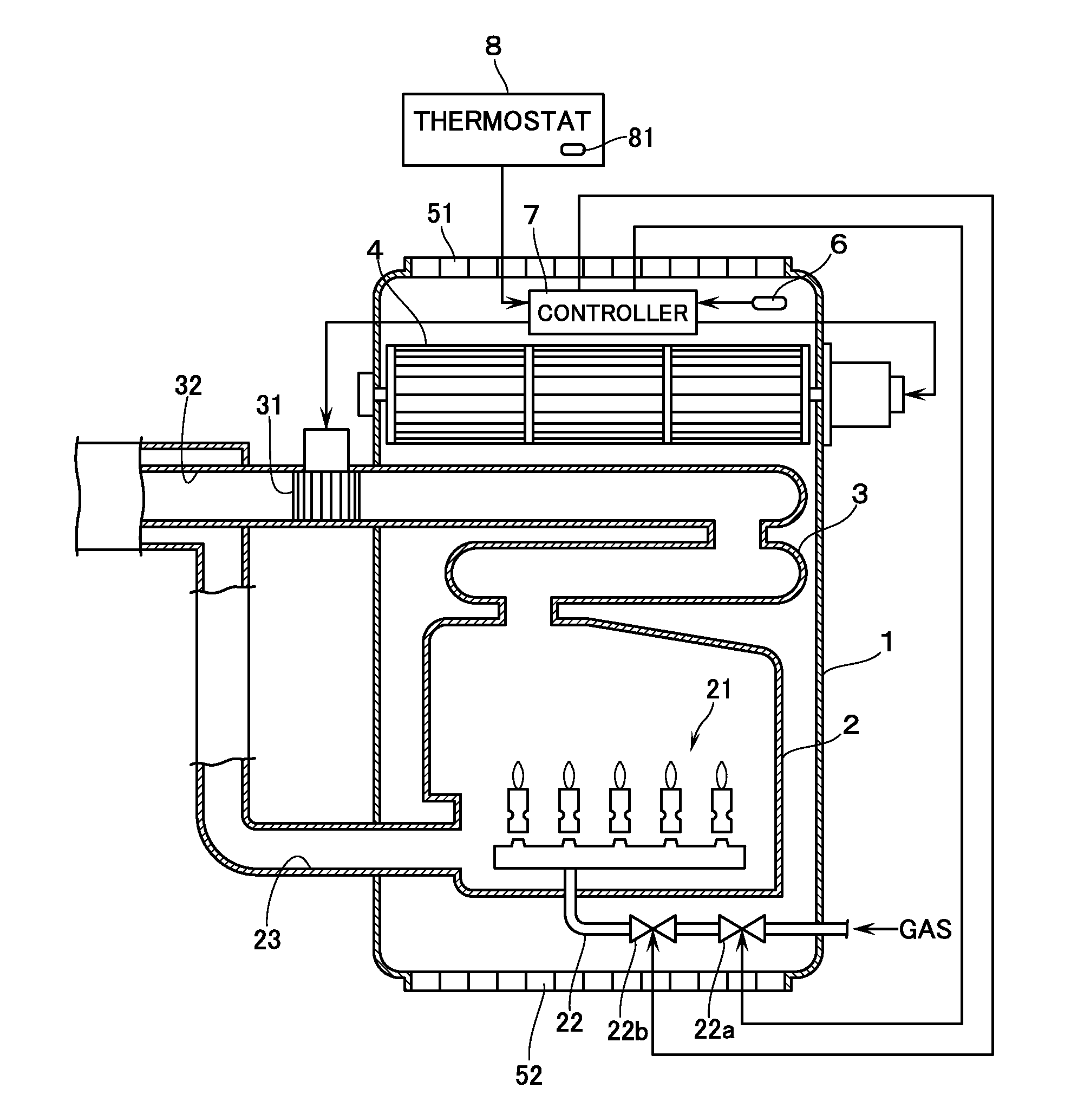
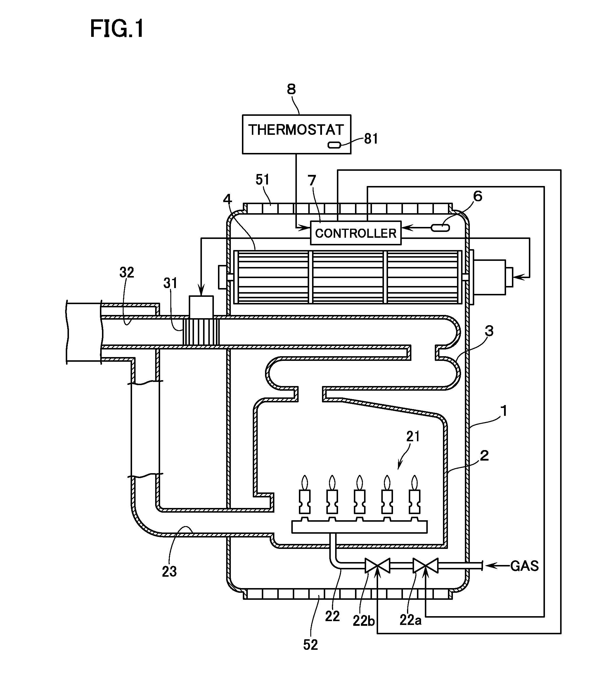
[0013]FIG. 1 illustrates a room heater 1 according to an embodiment of this invention. The room heater 1 contains therein: a combustion casing 2 having therein a burner 21; and a heat exchanger 3 in which combustion gas from the burner 21 flows. A supply passage 22 for supplying a fuel gas to the burner 21 has interposed therein: a solenoid valve 22a for opening / closing the supply passage 22; and a proportional valve 22b for varying the flow rate of the fuel gas. In this arrangement, air is supplied from an inlet passage 23 on an upstream of the combustion casing 2, and combustion gas is exhausted to an exhaust passage 32 via an exhaust fan 31 provided on a downstream of the heat exchanger 3. By operating a convection fan 4 provided above the heat exchanger 3, room air sucked from an air inlet 51 opened in a back face of the room heater 1 is heated by exchanging heat with the heat exchanger 3 and is then blown out of the room heater 1 as warm air from an air outlet 52 opened in a lo...


PUM


Abstract

A room heater is operated on receiving an on-command from a thermostat when a detected temperature detected by a second room-temperature detector falls below a first reference temperature, and is stopped on receiving an off-command when the temperature detected by the second room-temperature detector is above a second reference temperature that is set higher than the first reference temperature or when the thermostat is manually operated to be switched off. A setting temperature for temperature control to be carried out when the on-command is received again is updated according to a difference between the set temperature and the temperature detected by the first room-temperature detector on receiving the off-command. When the off-command is received before passing a predetermined period of time after receiving the on-command, the updating of the set temperature is prohibited if the temperature detected by the first room-temperature detector is below a predetermined minimum lower reference temperature.

Description

BACKGROUND[0001]1. Technical Field[0002]The present invention relates to a room heater including a room-temperature detecting means (a detector which detects a room temperature) and a control means (a controller) configured to control temperature by adjusting an amount of heat to be provided to room air according to a difference between a detected temperature detected by the room-temperature detecting means and a predetermined set temperature.[0003]2. Related Art[0004]As this kind of room heater, JP 2009-150591A discloses a room heater in which a control means is coupled to a thermostat that is also coupled to other appliances. The thermostat includes a second room-temperature detecting means provided independent of a first room-temperature detecting means of the room heater. The thermostat is configured to output an on-command when a detected temperature detected by the second room-temperature detecting means becomes a predetermined first reference temperature or below, and to outp...

Claims


Application Information

Patent Timeline
IPC IPC(8): F24D19/10
CPCF24D19/1084F24H3/065F24F11/30F24F11/62F24H9/2085F24F11/80F24F11/67F24H15/486F24H15/176F24H15/36F24H15/204F24H15/254F24H15/345F24H15/31G05D23/19
Inventor KANEIWA, SATOSHINISHIYAMA, SHIHORI
Owner RINNAI CORP
Why Eureka
Try Eureka