Circulating pump unit and solar thermal plant

a solar thermal plant and pump assembly technology, applied in solar heat collector controllers, space heating and ventilation details, domestic heating details, etc., can solve problems such as prone errors in the connection of sensors, and achieve the effect of reducing prone errors during operation, simplifying installation, and improving the construction of solar-thermal installations

Active Publication Date: 2019-12-17
GRUNDFOS HLDG
View PDF16 Cites 0 Cited by
  • Summary
  • Abstract
  • Description
  • Claims
  • Application Information

AI Technical Summary

Benefits of technology

[0004]It is therefore an object of the invention, to improve the construction of a solar-thermal installation, to the extent that the installation is simplified and the proneness to error during operation is reduced.
[0008]According to the invention, the control device is configured in a manner such that it approximately determines the temperature of the liquid in a liquid storage means connected to the circulation pump assembly via a heating circuit, on the basis of the temperature signal of the internal temperature sensor. This design has the advantage that one can make do without a temperature sensor on or in the liquid storage means itself. Instead, the temperature in the liquid storage means which is necessary e.g. for the control of the solar-thermal installation, is indirectly determined via the internal temperature sensor of the circulation pump assembly. The construction of such a solar-thermal installation is simplified by way of this, since one can make do without an external temperature sensor and its connection to the control device. Due to this measure, on the one hand the setting up of the installation is simplified, and on the other hand the reliability on operation of the installation is increased.
[0012]The communication interface of the control device can be configured as a wired-connected electrical communication interface, but for example can also be configured as an optical communication interface. Particularly preferably, the communication interface is configured as a wireless interface and in particular as a radio interface. By way of this, the installation effort is minimised, in particular on connection to components lying further away, since one can forgo a complicated wiring. The associated external components or devices which are to communicate with the communication interface of the control device, then usefully comprise correspondingly configured communication interfaces, i.e. as the case may be wire-connected or wireless interfaces. Particularly preferably, these devices also comprise radio interfaces. Thus, for example an external temperature sensor can be provided with a corresponding interface, in particular radio interface which in this manner can communicate with the control device via its communication interface. Thereby, at least one unidirectional communication from the sensor to the control device is provided. As the case may be, a bidirectional communication can be provided for example for coupling the external device to the control device. Such a bidirectional communication moreover lends itself if the external device is an actuator for example, such as a valve to be controlled.
[0013]According to a further preferred embodiment of the invention, the communication interface of the control device is configured for the automatic coupling to a communication interface of the at least one external device. Such a design is particularly advantageous if both parts, i.e. the control device and the external device are connected to one another for example via a network system or bus system, in which yet further components or devices are integrated. The control device and the external device then for example can preferably automatically recognize each other and automatically couple for communication, in such a network, for example a data network. Moreover, this design lends itself if the communication interfaces are configured as radio interfaces. Thus, the installation is simplified since both apparatus, when they have been put into operation, communicate with one another via corresponding signals such that they automatically recognize one another and couple automatically for communication with one another. Thus, for example an external temperature sensor can automatically locate and couple to the communication interface of the control device, in a manner such that the control device uses the temperature signal of this coupled external temperature sensor for the control or regulation. Such a coupling is indeed essential if several sensors or control devices are in reach, since then a fixed assignment is necessary, in order to be able to avoid any malfunctioning.
[0015]Particularly preferably, the control device of the circulation pump assembly according to the invention is configured for the control of a solar-thermal installation with at least one liquid storage means and at least one solar collector for heating the liquid in the liquid storage means, wherein the circulation pump assembly is envisaged for installation into a heating circuit between the liquid storage means and the solar module. In such an installation, the control device of the circulation pump assembly can assume the complete control or regulation of the solar-thermal installation, i.e. in particular can control or regulate the drive motor of the circulation pump assembly such that the liquid in the liquid storage means is heated by the solar collector in the desired manner. Thus, one can make do without an external control device, and the installation of the complete installation is significantly simplified. The control device is preferably integrated into the circulation pump assembly, by which means the assembly is particularly simplified. The control device of the circulation pump assembly can communicate with further external devices, e.g. as the case may be, control or regulate further pump assemblies, activate valves and, as the case may be, acquire data from external sensors such as flow sensors and / or temperature sensors and take this into account with the control or regulation of the solar-thermal installation or control or regulate the installation on the basis of the incoming measurement values.
[0020]The invention, apart from the previously described circulation pump assembly, also comprises a solar-thermal installation with at least one solar collector, at least one liquid storage means and at least one circulation pump assembly which is arranged in a heating circuit between the solar collector and the liquid storage means and which is designed according to the preceding description. The control device of the circulation pump assembly, as previously described, can assume the control of the complete solar-thermal installation, in such a solar-thermal installation. The arrangement of the integrated temperature sensor in the circulation pump assembly thereby has the previously described advantage that the temperature in the liquid storage means can be determined via this internal temperature sensor at least approximately, so that a temperature value for the temperature of the liquid in the liquid storage means is known for the control or regulation of the solar-thermal installation, without arranging a temperature sensor directly on or in the liquid storage means. The construction of the complete solar-thermal installation is simplified by way of this, since it is not necessary to assemble a temperature sensor in or on the liquid storage means and to connect it to the control device for the communication. The installation of the installation is simplified by way of this, the danger of incorrect installations is avoided and moreover the operational reliability of the installation is increased.

Problems solved by technology

Such connections of the sensors are prone to error with regard to assembly and in operation.

Method used


Image

  • Circulating pump unit and solar thermal plant
  • Circulating pump unit and solar thermal plant
  • Circulating pump unit and solar thermal plant

Examples


Embodiment Construction

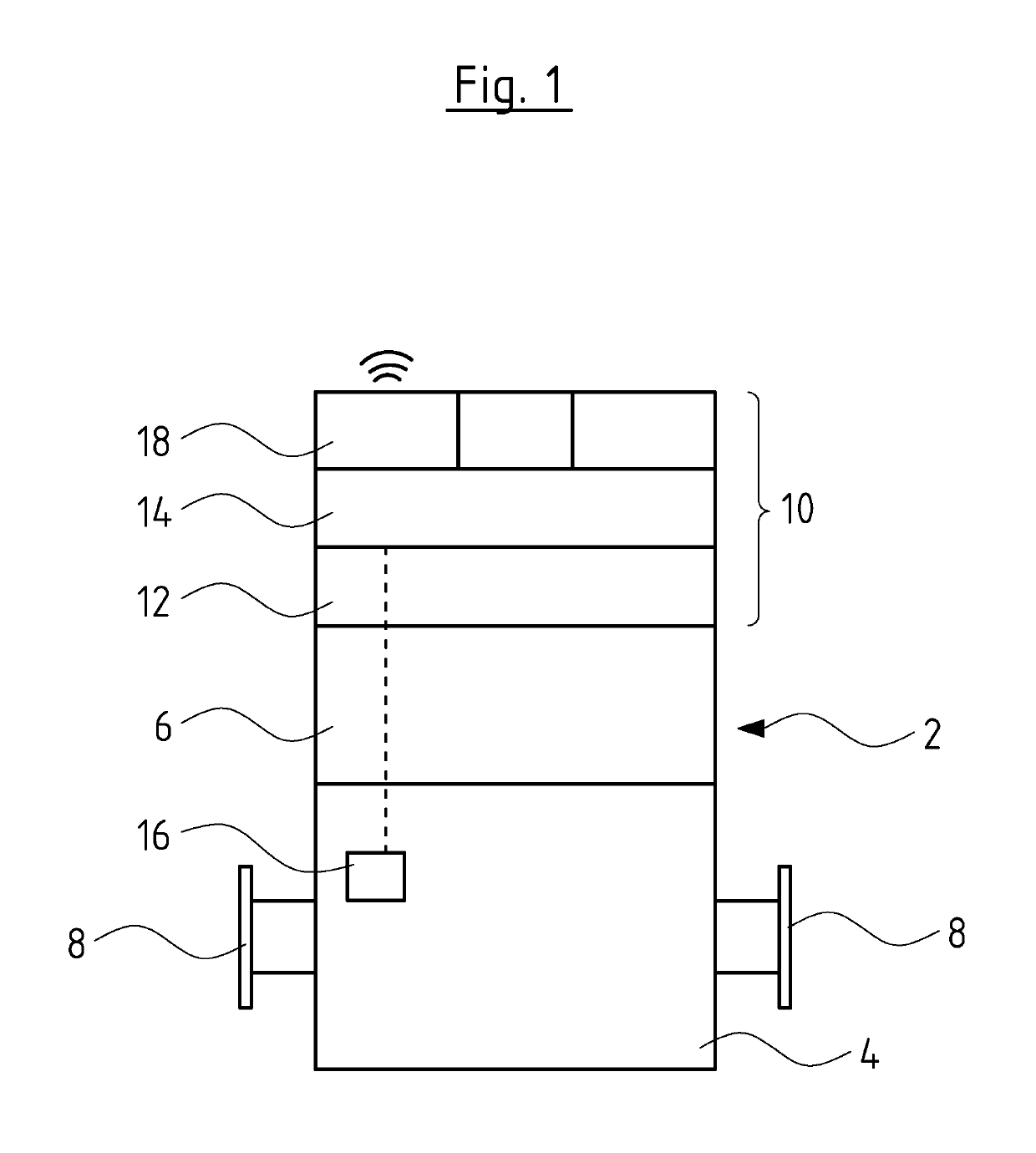
[0029]The circulation pump assembly 2 according to the invention, in the known manner comprises a pump housing 4 which contains an impeller of a centrifugal pump which is not shown here, and also comprises an electrical drive motor 6 which is connected to the pump housing 4 and which drives the at least one impeller in the pump housing 4. The pump housing comprises two connection nozzles (unions) 8, specifically an inlet nozzle and an outlet nozzle, for the connection to external pipe conduits.

[0030]The drive motor 6 in the known manner can be designed with a permanent magnet rotor and preferably as a canned motor.

[0031]A further constituent of the circulation pump assembly is a control device 10. The control device 10 is integrated into the pump assembly 2, for example in an electronics housing or terminal box, which is connected directly to the electrical drive motor 6 or together with this is arranged in an integrated housing. The control device 10 comprises a frequency converter...


PUM


Abstract

A circulation pump assembly (2) includes an electric drive motor (6) and a control device (10) integrated into the circulation pump assembly (2). At least one internal temperature sensor (16) is arranged in the circulation pump assembly (2) and detects the temperature of the medium delivered by the circulation pump assembly (6) and issues a corresponding temperature signal (42) to the control device (10). The control device (10) is configured, on the basis of the temperature signal (42) of the internal temperature sensor (16), to approximately determine the temperature of the liquid in a liquid storage means (26) which is connected to the circulation pump assembly (2) via a heating circuit (28).

Description

CROSS REFERENCE TO RELATED APPLICATIONS[0001]This application is a United States National Phase Application of International Application PCT / EP2014 / 058595 filed Apr. 28, 2014 and claims the benefit of priority under 35 U.S.C. § 119 of European Patent Application 13 168 535.6 filed May 21, 2013 the entire contents of which are incorporated herein by reference.FIELD OF THE INVENTION[0002]The invention relates to a circulation pump assembly as well as to a solar-thermal installation with such a circulation pump assembly.BACKGROUND OF THE INVENTION[0003]Solar-thermal installations comprise at least one solar collector and a water storage means, in which for example service water to be heated is stored. The solar collector is connected to a heat exchanger arranged in or on the water storage, via a heating circuit, in which a circulation pump delivering the heating medium heated by the solar collector into the heat exchanger of the water storage means and back out of this into the solar c...

Claims


Application Information

Patent Timeline
Patent Type & Authority Patents(United States)
IPC IPC(8): F04D27/00F24S50/40F04D15/00F24D17/00F24S90/00
CPCF04D15/0066F24S50/40F04D27/007F04D27/006F24D17/0068F04D15/0263Y02B10/20Y02B10/70F24D19/1057F24D2200/08F24D2200/14F24D2220/042F24D2220/0207F24S60/30Y02E10/40F24S90/00F24D17/0015
Inventor MORTENSEN, LARS SUNDJENSEN, KIM HULEGAARD
Owner GRUNDFOS HLDG
Why Eureka
Try Eureka