Method of producing honeycomb structural body

a technology of structural body and honeycomb, which is applied in the direction of butter manufacturing, ceramic extrusion dies, machines/engines, etc., can solve the problems of generating cell defects, complex design of metal dies, and breaking metal dies, and achieves the effect of reducing the generation of local high stress, high shaping pressure, and increasing the feeding pressure of raw materials

Active Publication Date: 2015-05-21
DENSO CORP
View PDF8 Cites 17 Cited by
  • Summary
  • Abstract
  • Description
  • Claims
  • Application Information

AI Technical Summary

Benefits of technology

[0012]In the projection section of the first metal die in the metal die used by the method, the raw material is fed from the feeding surface, and smoothly extruded from the first slits on the extrusion surface through the raw material first feeding holes. On the other hand, the raw material, which has passed through the raw material second feeding holes in the first metal die, is extruded from the second slits in the second metal die through the communication holes. The raw material second feeding holes communicate with the communication holes. In particular, it is possible for the surface of the second metal die to receive a deformation stress of the first metal die generated during the shaping step. It is possible for the structure of the metal die to suppress generation of a local high stress in the metal die when a shaping pressure (i.e. a feeding pressure) of the raw material is increased during the shaping step. Accordingly, it is possible for the method according to the exemplary embodiment to perform the shaping step at a high shaping pressure (i.e. the feeding pressure) without damage and deformation of the metal die, and produce the honeycomb structural body with excellent productivity.

Problems solved by technology

However, these techniques require a complicated design for producing a metal die for use in the production of such a complicated structure of the honeycomb structural body.
Further, there is a possible drawback of breaking the metal die when the honeycomb structural body is produced, and generating defects of cells during the production of the produced honeycomb structural body.
In fact, it is difficult to produce a honeycomb structural body having a complicated structure by using a metal die.
However, in the structure of the metal die used in the patent document, a high local stress is generated the fitted section between the inside metal die and the outside metal die, and as a result, the metal die is broken by a high local stress when the metal die is used for producing a honeycomb structural body.
In addition, it is generally difficult to correctly mate feeding holes formed in the inside metal die with feeding holes formed in the outside metal die, and to produce the metal die having such a complicated structure.
That is, it is difficult to produce a metal die corresponding to a complicated and various types of cell structures of a honeycomb structural body.

Method used


Image

  • Method of producing honeycomb structural body
  • Method of producing honeycomb structural body
  • Method of producing honeycomb structural body

Examples


first exemplary embodiment

[0042]A description will be given of a method of producing a honeycomb structural body 5 according to a first exemplary embodiment with reference to FIG. 1 to FIG. 19.

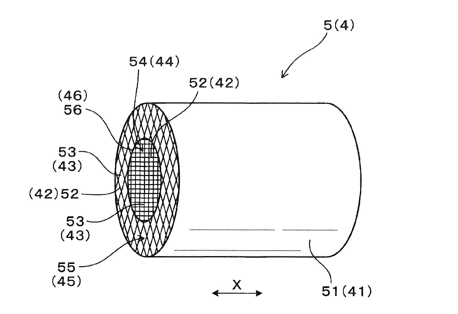
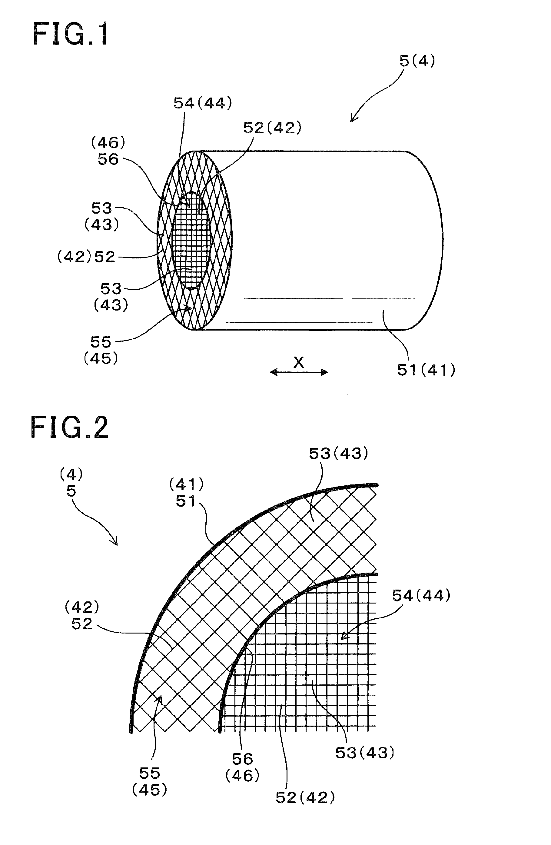
[0043]FIG. 1 is a perspective view showing the honeycomb structural body 5 (or a honeycomb molded body) produced by the method according to the first exemplary embodiment. FIG. 2 is a view showing a cross section of the honeycomb structural body 5 produced by the method according to the first exemplary embodiment in a direction perpendicular to an axial direction of the honeycomb structural body 5.

[0044]As shown in FIG. 1 and FIG. 2, the method according to the first exemplary embodiment produces the honeycomb structural body 5. The honeycomb structural body 5 is comprised of an outer skin layer 51 having a cylindrical shape, cell walls 52 arranged in the outer skin layer 51 and a plurality of cells 53 surrounded by the cell walls 52. The cell walls 52 are arranged in a square lattice like shape in the outer skin layer...

second exemplary embodiment

[0089]A description will be given of the second exemplary embodiment with reference to FIG. 20 and FIG. 21.

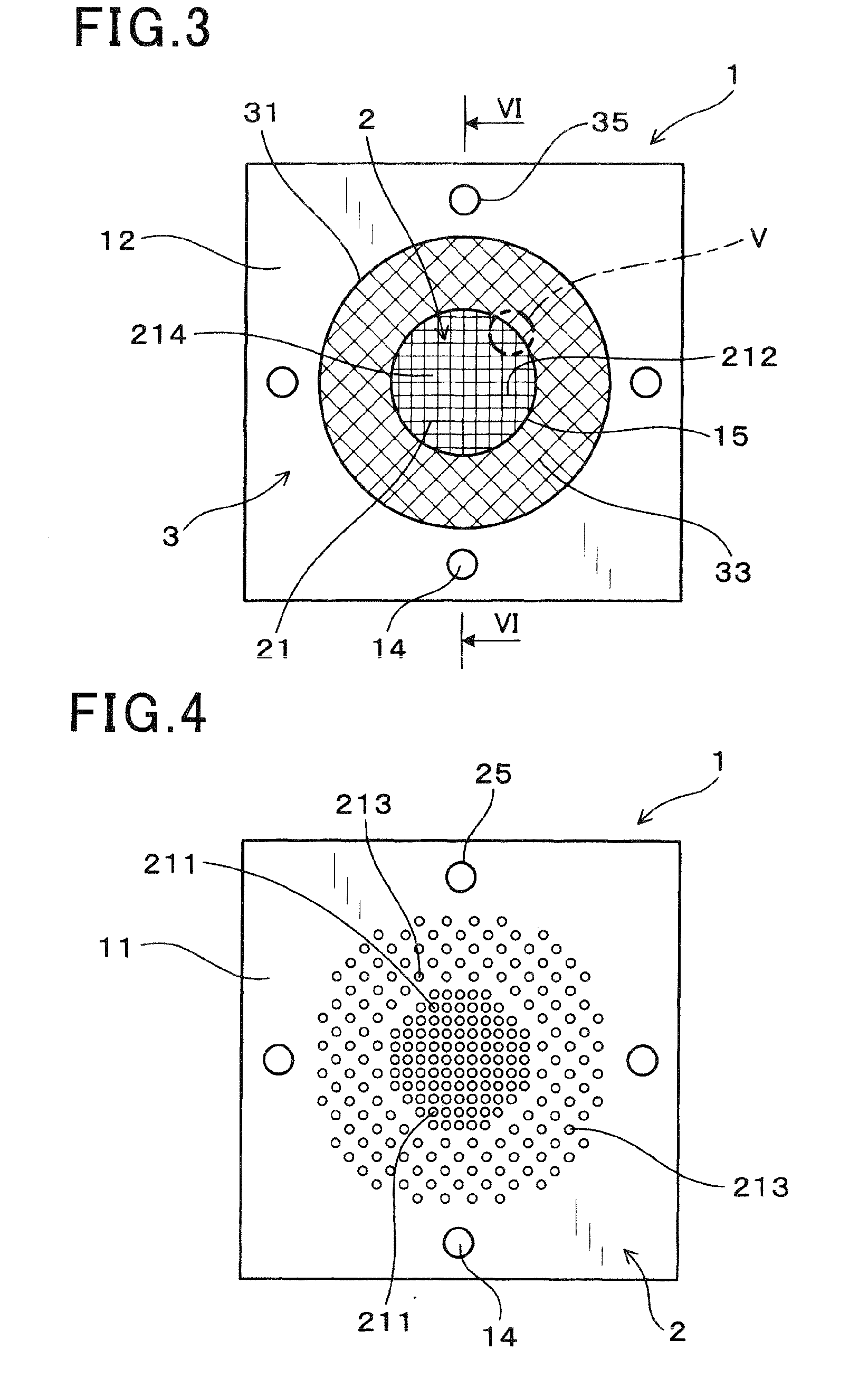
[0090]The second exemplary embodiment evaluates a degree in deformation or displacement between the first metal die 2 and the second metal die 3 in the metal die 1 when raw material is extruded through the metal die 1 composed of the first metal die 2 and the second metal die 3. That is, the second exemplary embodiment performs the evaluation test using the metal die 1 having the structure previously explained in the first exemplary embodiment, and the following explanation will use the same reference numbers and characters used in the first exemplary embodiment.

[0091]The second exemplary embodiment prepared various types of metal dies as evaluation test samples. Each of the evaluation test samples basically has the same components of the metal die 1 according to the first exemplary embodiment, but has a different thickness ratio of the first metal die 2 and the second metal di...


PUM

PropertyMeasurementUnit
porosityaaaaaaaaaa
thicknessaaaaaaaaaa
heightaaaaaaaaaa

Abstract

A method feeds raw material into a metal die and extrudes the raw material to produce a honeycomb molded body. The method fires the honeycomb molded body to make a honeycomb structural body. The metal die has a first metal die and a second metal die arranged at an upstream side of an extrusion direction of the raw material and a second metal die arranged at a downstream side of the extrusion direction of the raw material. The first metal die has a projection section and the second metal die has a penetration hole. The projection section is fitted to the penetration hole to assemble the first metal die and the second metal die. Communication holes formed in the second metal die communicate with raw material second feeding holes formed in the first metal die.

Description

CROSS-REFERENCE TO RELATED APPLICATION[0001]This application is related to and claims priority from Japanese Patent Application No. 2013-236965 filed on Nov. 15, 2013, the contents of which are hereby incorporated by reference.BACKGROUND OF THE INVENTION[0002]1. Field of the Invention[0003]The present invention relates to methods of extruding a raw material to shape a honeycomb molded body and fire the honeycomb molded body to produce a honeycomb structural body.[0004]2. Description of the Related Art[0005]A honeycomb structural body has been widely known to support catalyst therein. The catalyst has a purification property. In general, such a honeycomb structural body has cell walls arranged in a lattice like shape and a plurality of cells surrounded by the cell walls. When the honeycomb structural body supports catalyst therein and is mounted on an exhaust gas pipe in an exhaust gas purification system of a motor vehicle, etc., the catalyst supported in the honeycomb structural bo...

Claims


Application Information

Patent Timeline
Patent Type & Authority Applications(United States)
IPC IPC(8): B28B3/26C04B35/64B28B3/20C04B38/00B29C48/30
CPCB28B3/269C04B38/0006B28B2003/203B28B3/20C04B35/64C04B2111/0081C04B35/195C04B35/565C04B2235/6021F01N3/2828F01N2330/48F01N13/017B01D46/0001B29C48/11B29C48/304B29C48/49B01D46/2496B01D46/2462
Inventor HAYASHI, NAOHIRO
Owner DENSO CORP
Why Eureka
Try Eureka