Rotor for rotating electric machine

Active Publication Date: 2015-05-21
DENSO CORP
View PDF8 Cites 25 Cited by
  • Summary
  • Abstract
  • Description
  • Claims
  • Application Information

AI Technical Summary

Benefits of technology

[0020]With the above structure of the second rotor, the corresponding permanent magnet is held between the first and second supporting portions in the circumferential direction of the rotor core. Consequently, in operation, it is possible to disperse thermal stresses, which are repeatedly induced respectively in the first and second supporting portions by heat generated by the corresponding permanent magnet, respectively toward opposite sides in the circumferential direction, thereby ensuring high strength of the rotor core.
[0021]Moreover, with the above structure of the second rotor, it is possible to minimize both the gap between the second magnetic flux bar

Problems solved by technology

However, in operation of an IPM motor as described above, the permanent magnets generate heat with rotation of the rotor, causing the temperature of the rotor core to increase.

Method used


Image

  • Rotor for rotating electric machine
  • Rotor for rotating electric machine
  • Rotor for rotating electric machine

Examples


Example

First Embodiment

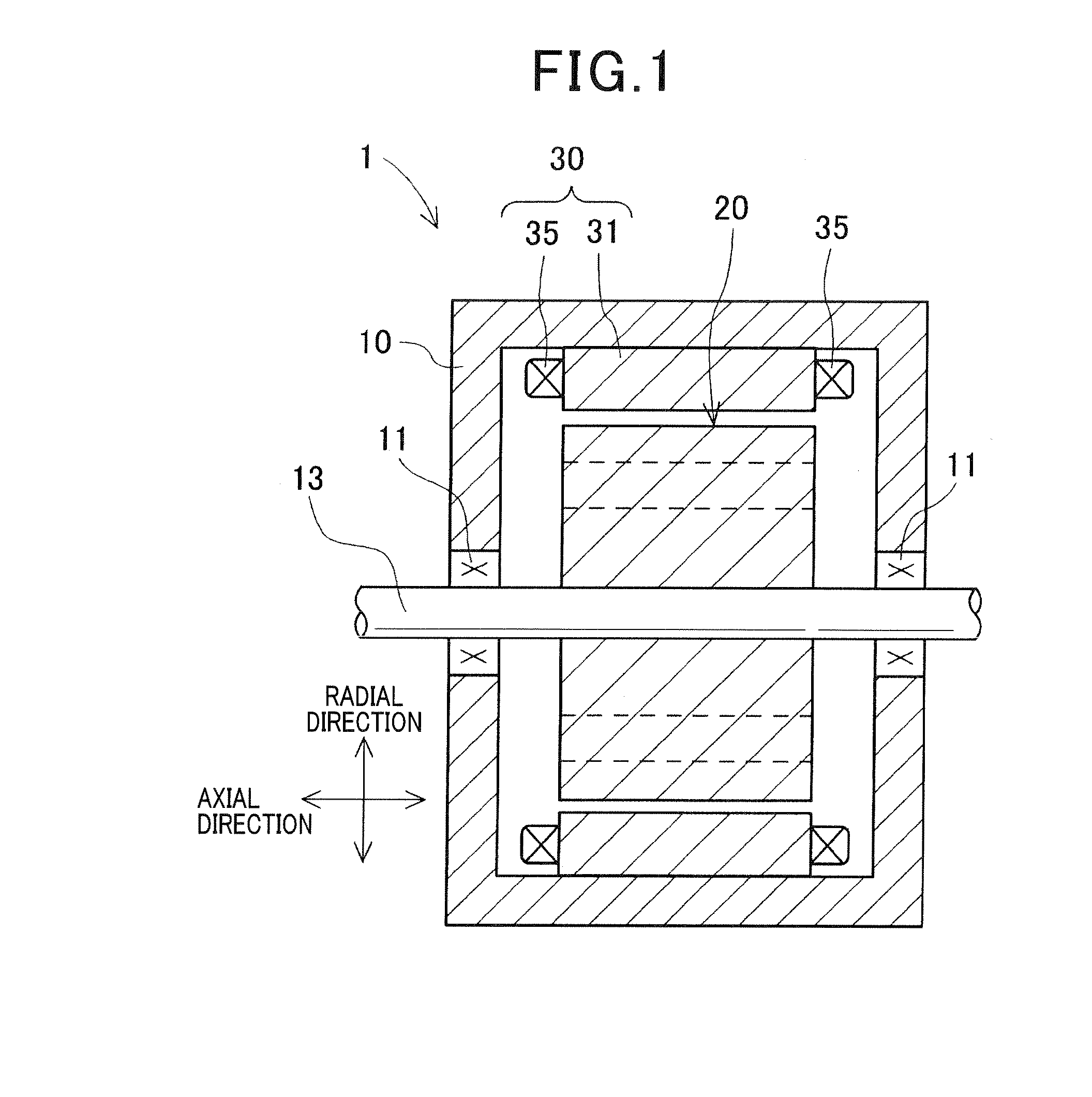
[0033]FIG. 1 shows the overall configuration of a rotating electric machine 1 which includes a rotor 20 according to the first embodiment.

[0034]In the present embodiment, the rotating electric machine 1 is configured as an inner rotor-type electric motor for use in, for example, a motor vehicle. As shown in FIG. 1, the rotating electric machine 1 further includes, in addition to the rotor 20, a housing 10, a rotating shaft 13 and a stator 30.

[0035]The housing 10 has a substantially hollow cylindrical shape with both ends closed. The rotating shaft 13 has its end portions respectively rotatably supported by axial end walls of the housing 10 via bearings 11. On the outer periphery of a central portion of the rotating shaft 13 which is received in the housing 10, there is fixedly fitted the rotor 20 so as to be rotatable together with the rotating shaft 13. The structure of the rotor 20 will be described in detail later.

[0036]The stator 30 includes an annular stator cor...

Example

Second Embodiment

[0061]This embodiment illustrates a rotor 20A which has a similar structure to the rotor 20 according to the first embodiment; accordingly, only the differences therebetween will be described hereinafter.

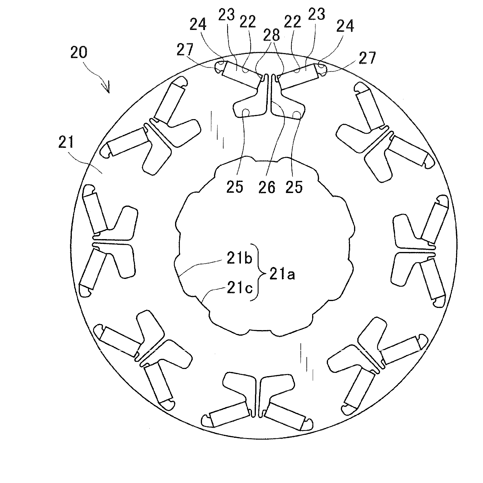
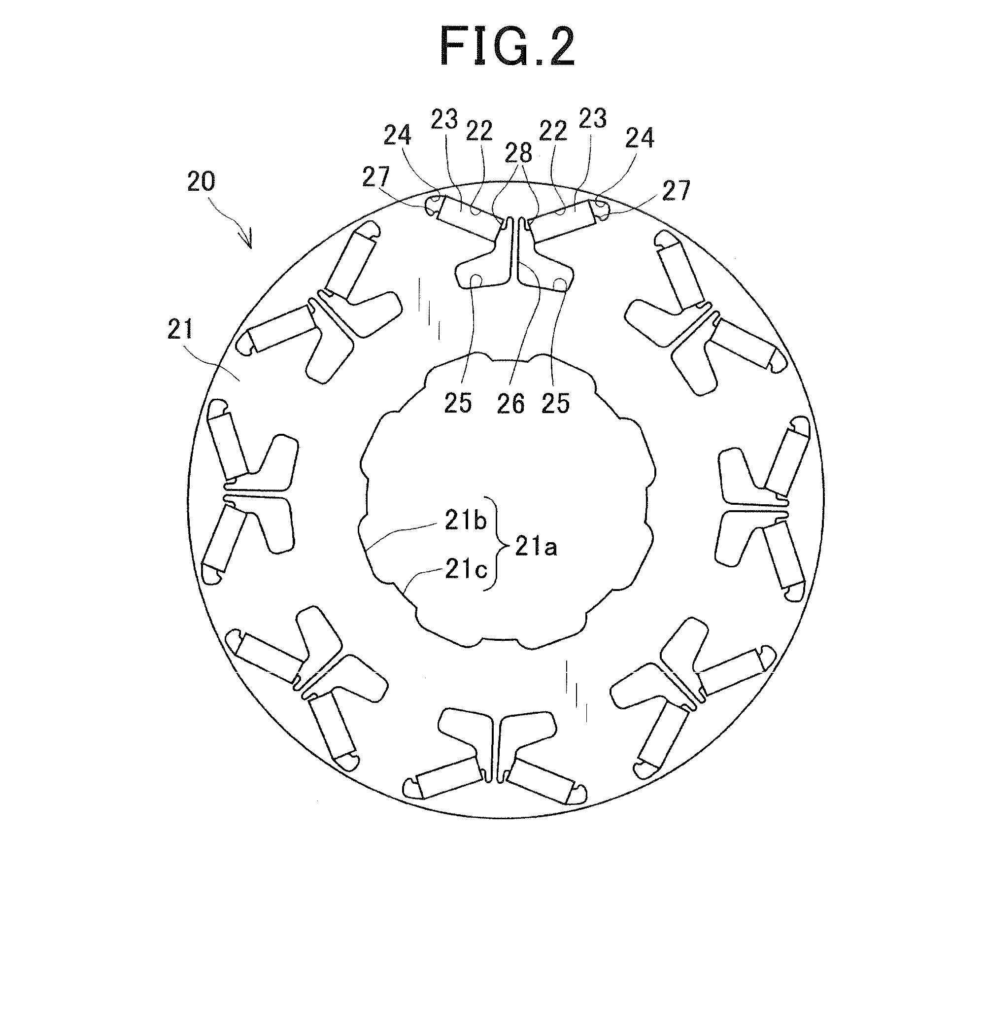
[0062]In the first embodiment, as described previously, for each of the magnet-receiving holes 22 of the rotor core 21, there are formed in the rotor core 21 both the first and second supporting portions 27 and 28 that support the corresponding permanent magnet 23 received in the magnet-receiving hole 22. More specifically, the first supporting portion 27 is formed at the radially inner end of the first magnetic flux barrier 24 so as to support the radially inner end portion of the first magnetic flux barrier-side face 23a of the corresponding permanent magnet 23. The second supporting portion 28 is formed at the radially outer end of the second magnetic flux barrier 25 so as to support the radially outer end portion of the second magnetic flux barrier-side face 23b...


PUM


Abstract

A rotor includes a rotor core that has magnet-receiving holes in each of which is received a corresponding permanent magnet. The rotor core also has, for each of the magnet-receiving holes, first and second supporting portions. The first supporting portion supports a radially inner end portion of a first magnetic flux barrier-side face of the corresponding permanent magnet. The second supporting portion supports a radially outer end portion of a second magnetic flux barrier-side face of the corresponding permanent magnet. A second magnetic flux barrier-side end portion of a radially outer wall surface of the magnet-receiving hole is planar in shape and parallel to a radially outer side face of the corresponding permanent magnet. A second magnetic flux barrier-side end portion of a radially inner wall surface of the magnet-receiving hole is planar in shape and parallel to a radially inner side face of the corresponding permanent magnet.

Description

CROSS-REFERENCE TO RELATED APPLICATION[0001]This application is based on and claims priority from Japanese Patent Application No. 2013-236519 filed on Nov. 15, 2013, the content of which is hereby incorporated by reference in its entirety into this application.BACKGROUND[0002]1. Technical Field[0003]The present invention relates to rotors for rotating electric machines that are used in, for example, motor vehicles as electric motors and electric generators.[0004]2. Description of Related Art[0005]There are known IPM (Interior Permanent Magnet) motors that have permanent magnets embedded in a rotor core. The IPM motors can use both reluctance torque and magnetic torque, thereby achieving high efficiency. Therefore, the IPM motors are particularly suitable for use in hybrid and electric vehicles.[0006]An IPM motor generally includes a stator and a rotor that is disposed in radial opposition to the stator. The rotor includes a rotor core and a plurality of permanent magnets. The rotor ...

Claims


Application Information

Patent Timeline
IPC IPC(8): H02K1/27
CPCH02K1/274H02K1/2766H02K1/28H02K1/32H02K9/197
Inventor TAKAHASHI, YUKI
Owner DENSO CORP
Why Eureka
Try Eureka