
Network video monitoring system and method for automatically assigning cameras in the same

a video monitoring system and network video technology, applied in the field of network video monitoring system and automatic assignment method of the monitoring system, can solve the problems of inability of related art monitoring system to automatically conduct the transfer of control right, vulnerable to internet hacker, etc., to achieve balanced load of nvr hosts, save manual setting up labor, and balance system load

Inactive Publication Date: 2015-05-21
DELTA ELECTRONICS INC
View PDF3 Cites 12 Cited by
  • Summary
  • Abstract
  • Description
  • Claims
  • Application Information

AI Technical Summary

Benefits of technology

The present invention provides a network video monitoring system and method where cameras can be dynamically assigned to corresponding NVR host according to their statuses and the quality of the camera. This helps to balance the load on the NVR hosts and prevents overloaded NVR host from malfunctions. Additionally, if one NVR host malfunctions, the control right of the cameras controlled by it can be transferred to another NVR host with normal operation. The system is easy to set up, reduces the risk of hacker attacks and other security threats.

Problems solved by technology

In other words, the related art monitoring system cannot automatically conduct the transfer of control right.
Moreover, when a NVR host 6 malfunctions, the system manager also needs to manually fix the problem because the related art monitoring system cannot automatically fix the problem.
The NVR hosts 6 in related art monitoring have public IP address and are vulnerable to Internet hacker.

Method used


Image

  • Network video monitoring system and method for automatically assigning cameras in the same
  • Network video monitoring system and method for automatically assigning cameras in the same
  • Network video monitoring system and method for automatically assigning cameras in the same

Examples


first embodiment

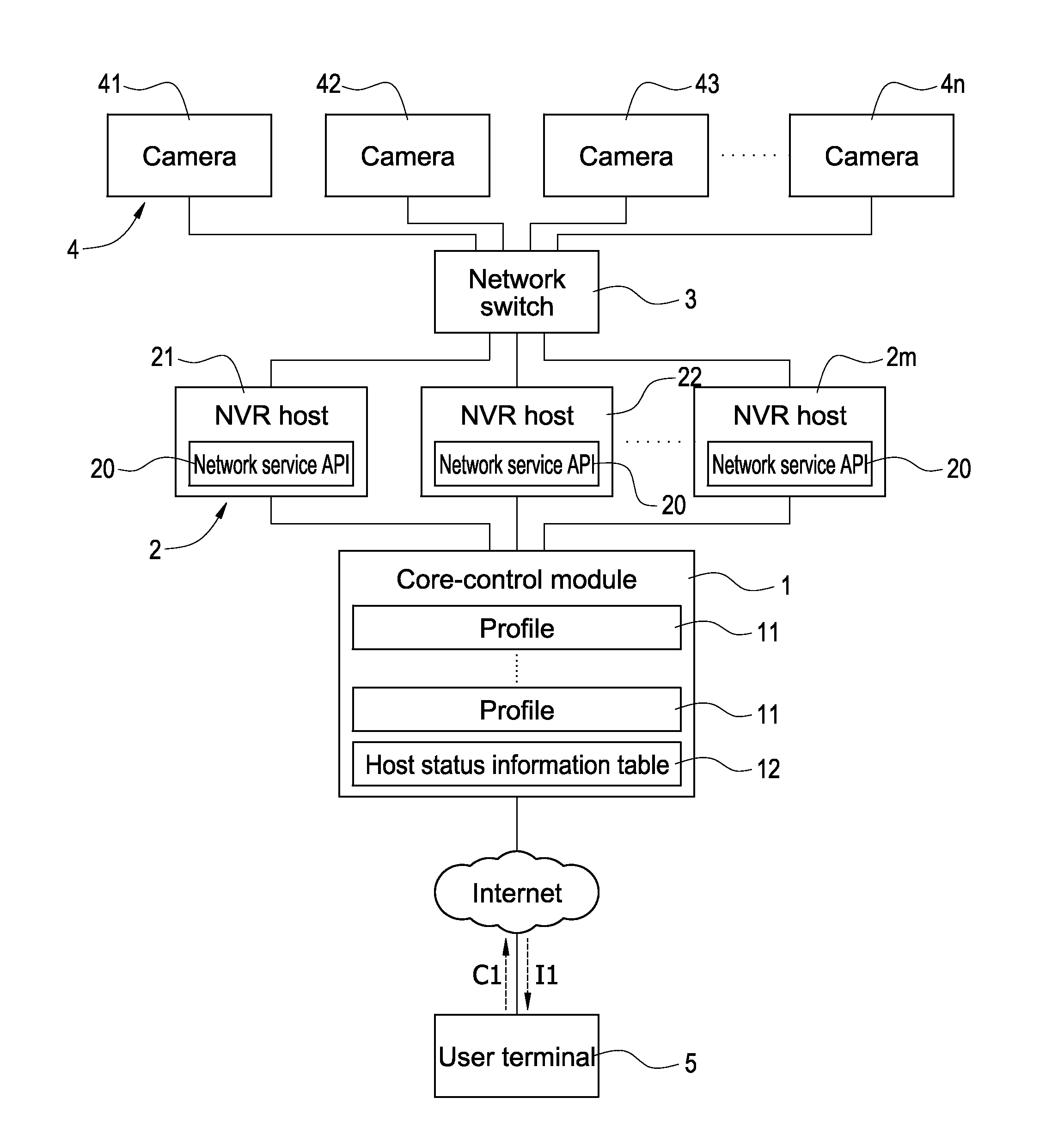
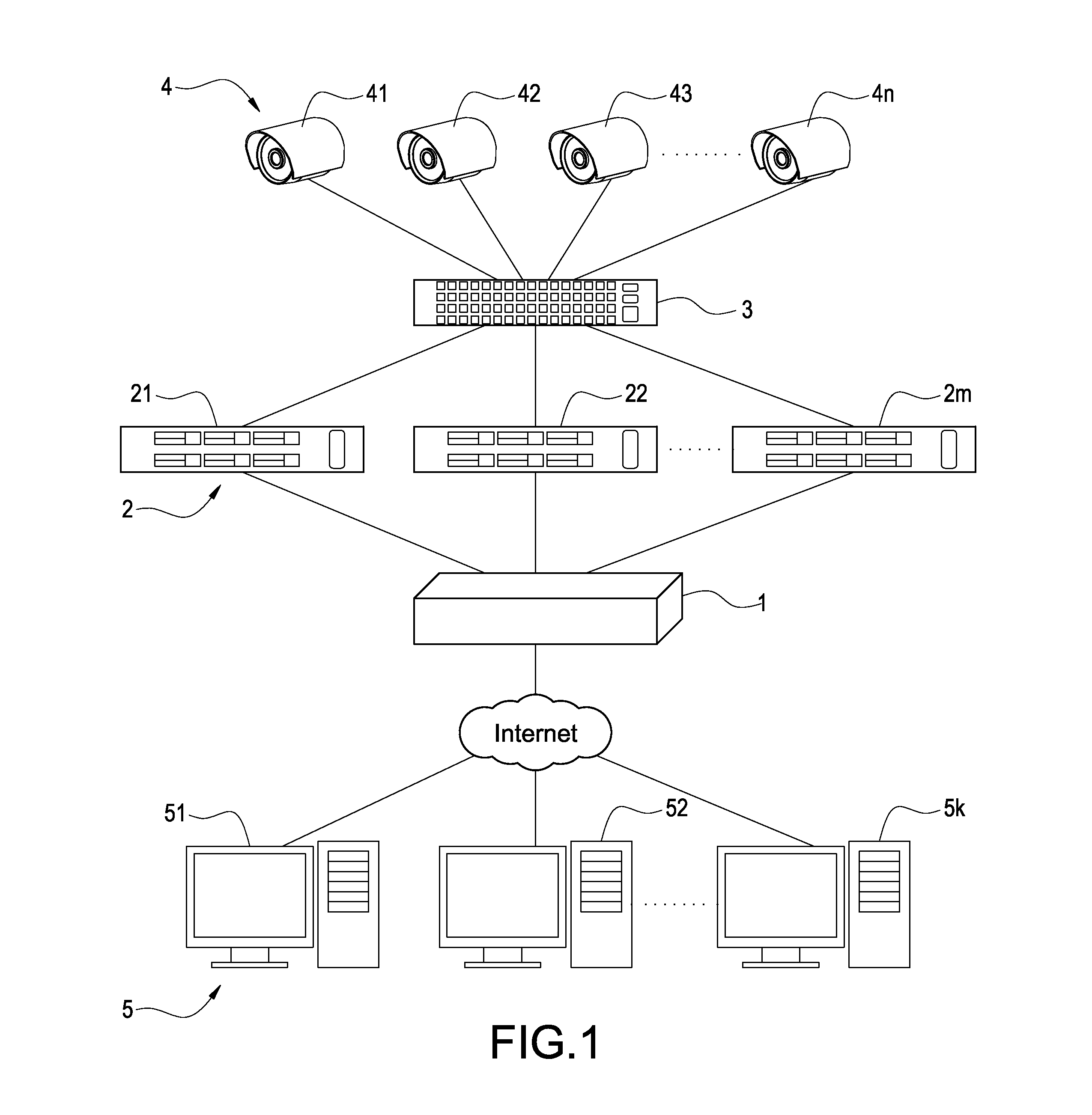
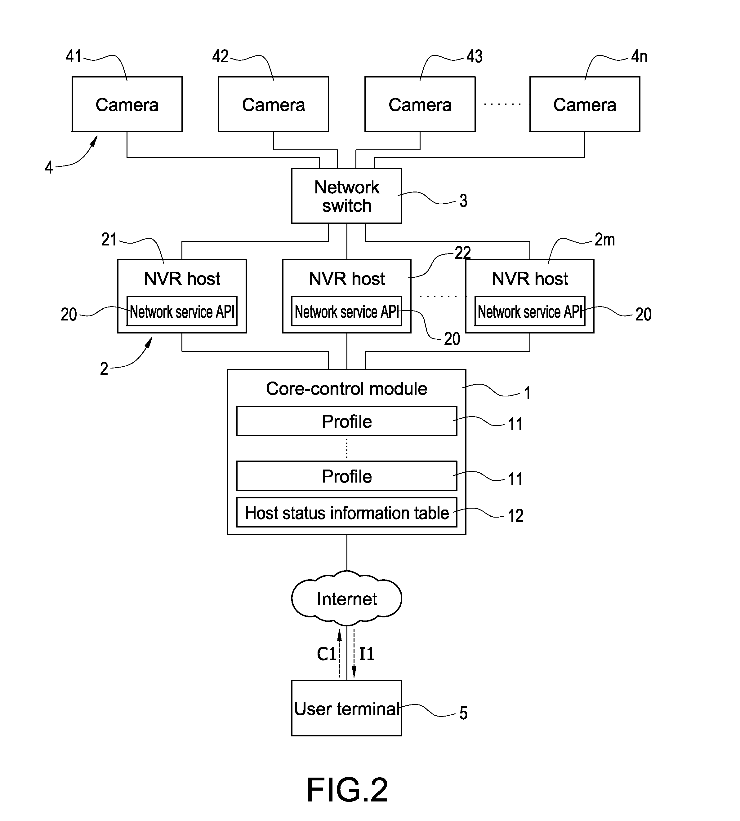
[0043]FIG. 3 shows a supplementary flowchart for the present invention, the physical NVR hosts 21-2m and cameras 41-4n are disposed at suitable locations if more NVR host and camera are needed (step S10). Afterward, the system manager records the IP address of the NVR hosts 21-2m and the profiles 11 of the cameras 41-4n to the core-control module 1 (step S12). The core-control module 1 then operatively connects to the NVR hosts 21-2m according to the IP addresses stored therein and respectively inquires the status of the NVR hosts 21-2m (step S14), wherein the status of the NVR hosts 21-2m includes, but not limited to, loading, CPU using rate, hard disk space and network bandwidth of the NVR hosts 21-2m.

[0044]Afterward, the core-control module 1 dynamically assigns each of the cameras 41-4n to one of the NVR hosts 21-2m for control thereof. Depending on the assignment, each of the NVR hosts 21-2m can control one or more camera 4.

[0045]In the present embodiment, the core-control mod...

second embodiment

[0070]FIG. 13 shows the system diagram according to the present invention. The system shown in FIG. 13 is similar to that shown in FIG. 2 except that one NVR host 2′ in FIG. 13 is further installed with the core-control module 1 while other NVR hosts (such as the first NVR host 21 and the second NVR host 22) are not. Therefore, the other NVR hosts 21 and 22 are operatively connected to the NVR host 2′ installed with the core-control module 1 and communicates with the core-control module 1. Moreover, the NVR host 2′ is operatively connected to both private domain and Internet such that the NVR host 2′ is operatively connected to the other NVR hosts 21 and 22, the network switch 3, and the cameras 41-4n through private domain, and connected to the user terminals 5 through Internet.


PUM


Abstract

A network video monitoring system includes a core-control module, a plurality of network video recording (NVR) hosts, and a plurality of cameras. The core-control module assigns the cameras to the NVR hosts respectively for controlling the camera by the NVR hosts according to status of each NVR host. In this application, the core-control module obtains the status of each NVR host periodicity for determining if the NVR hosts are over loading or failed, and re-assigns the cameras automatically for the overloaded or malfunctioned NVR hosts. The application rescues the NVR hosts from the over loading problem, and prevents the termination of the monitoring action of the cameras when one of the NVR host malfunctions.

Description

BACKGROUND OF THE INVENTION[0001]1. Field of the Invention[0002]The present invention relates to monitoring system, especially to network video monitoring system and automatic assignment method for the monitoring system.[0003]2. Description of Related Art[0004]In a monitoring system, cameras generally only fetch locale image, and therefore, the cameras are controlled by a rear-end host to fetch image and store the fetched image. Moreover, user of the system generally views the monitored image of the camera and plays back the recorded file through operating the host.[0005]FIG. 14 shows a related art monitoring system, which comprises a plurality of network video recording (NVR) hosts 6, a network switch 7 and a plurality of cameras 8. The NVR hosts 6 are connected to the network switch 7 and further connected to the cameras 8 through the network switch 7.[0006]The monitoring system needs lots of NVR hosts 6 to control the monitoring and recording tasks of the cameras respectively whe...

Claims


Application Information

Patent Timeline
Patent Type & Authority Applications(United States)
IPC IPC(8): H04N7/18H04L12/24H04L29/08
CPCH04N7/181H04L41/08H04L67/12H04N5/76H04N5/77
Inventor HSIEH, TUNG-YICHAN, CHIA-CHING
Owner DELTA ELECTRONICS INC
Learn More