Receptacle connector and method of producing receptacle connector

a technology of receptacle connector and receptacle connector, which is applied in the direction of two-part coupling devices, coupling device connections, printed circuits, etc., can solve the problems of reducing the force to hold an engaged state between the receptacle connector and the plug connector, and affecting the operation of the operator

Inactive Publication Date: 2015-05-21
KYOCERA CORP
View PDF1 Cites 59 Cited by
  • Summary
  • Abstract
  • Description
  • Claims
  • Application Information

AI Technical Summary

Benefits of technology

[0014]The present invention provides a receptacle connector and a method of producing a receptacle connector, even though each receptacle-side metal fixing member is firmly engageable with the plug connector even after the receptacle connector and the plug connector are connected and disconnected a plurality of times, the strength of the fixation of each receptacle-side metal fixing member to the receptacle insulator of the receptacle connector can be increased even when the connector, which is configured of the receptacle connector and an associated plug connector, is miniaturized.

Problems solved by technology

In the case where either the receptacle-side metal fixing members or the plug-side metal fixing members are provided with no resilient contact portions, the possibility of the receptacle-side metal fixing members and / or the plug-side metal fixing members getting scratched or damaged becomes high if only the receptacle connector and the plug connector are connected once.
If the receptacle-side metal fixing members and / or the plug-side metal fixing members get scratched or damaged, the engaging force between each receptacle-side metal fixing member and the associated plug-side metal fixing member when the receptacle-side metal fixing members and the plug-side metal fixing members are re-connected to each other after being connected to and then disconnected from each other deteriorates, so that the force to hold an engaged state between the receptacle connector and the plug connector may deteriorate, and the operator may not be able to feel the tactile click.
Additionally, the rigidity of the receptacle insulator easily decreases due to the shape of the receptacle insulator (the shape of the periphery of the aforementioned mounting holes, etc.) becoming so complicated that a thin-wall portion(s), etc., are formed.
Accordingly, there is a possibility of the receptacle insulator being deformed or damaged when the receptacle connector and the connector are connected.
Additionally, resin flowability (moldability) easily decreases due to the complicated shape of the receptacle insulator, which is not favorable in terms of productivity.

Method used


Image

  • Receptacle connector and method of producing receptacle connector
  • Receptacle connector and method of producing receptacle connector
  • Receptacle connector and method of producing receptacle connector

Examples


Embodiment Construction

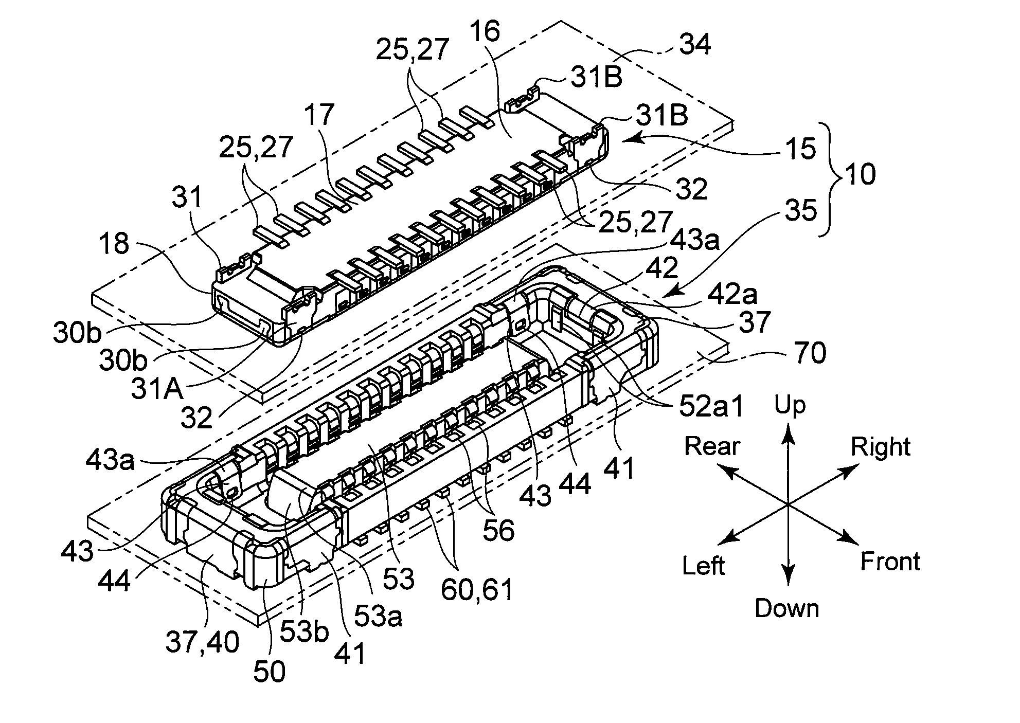
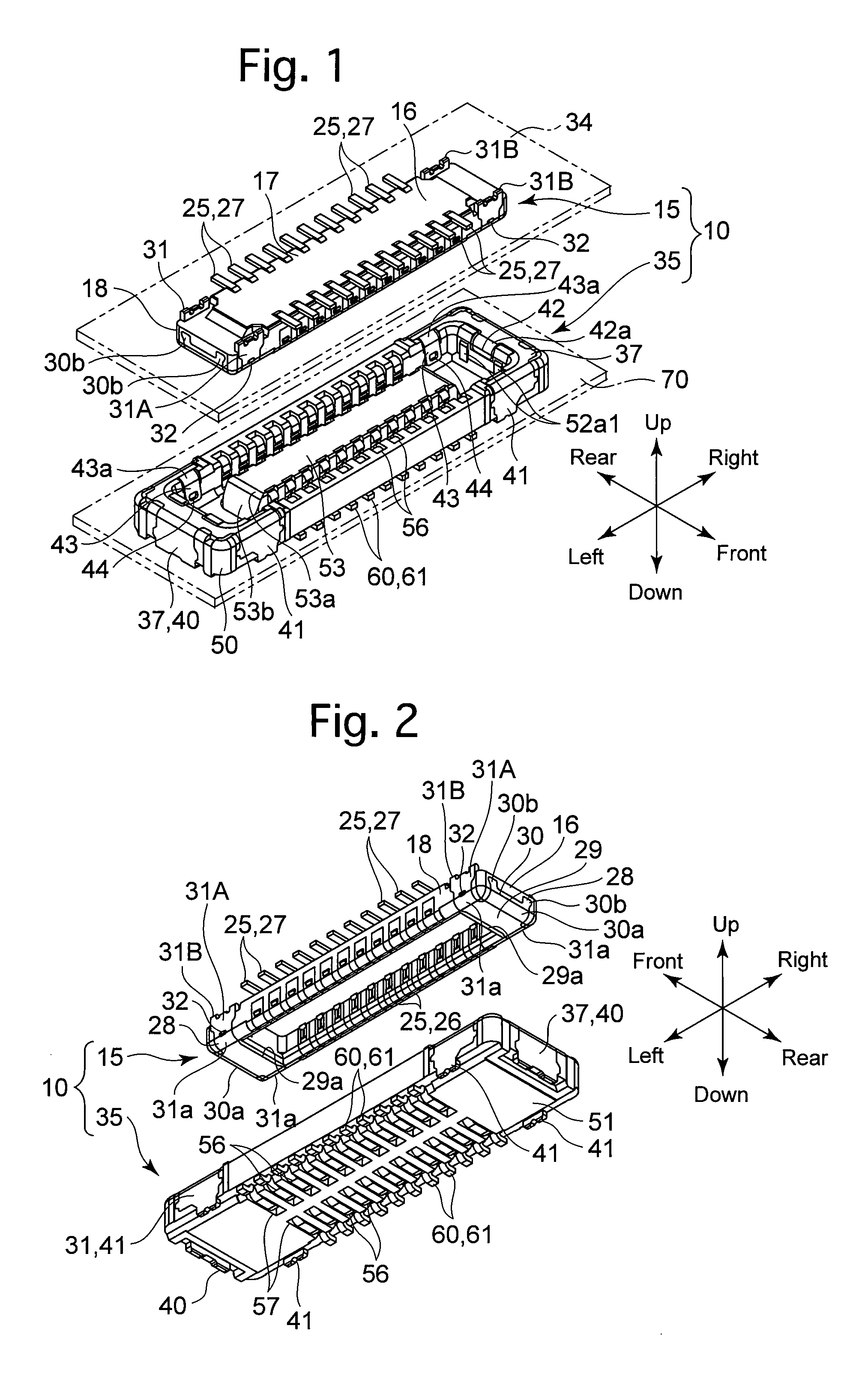
[0047]An embodiment of a connector according to the present invention will be hereinafter discussed with reference to FIGS. 1 through 16. In the following descriptions, forward and rearward directions, leftward and rightward directions, and upward and downward directions of the connector 10 are determined with reference to the directions of the double-headed arrows shown in the drawings.

[0048]The present embodiment of the connector 10 is provided with a plug connector 15 and a receptacle connector 35.

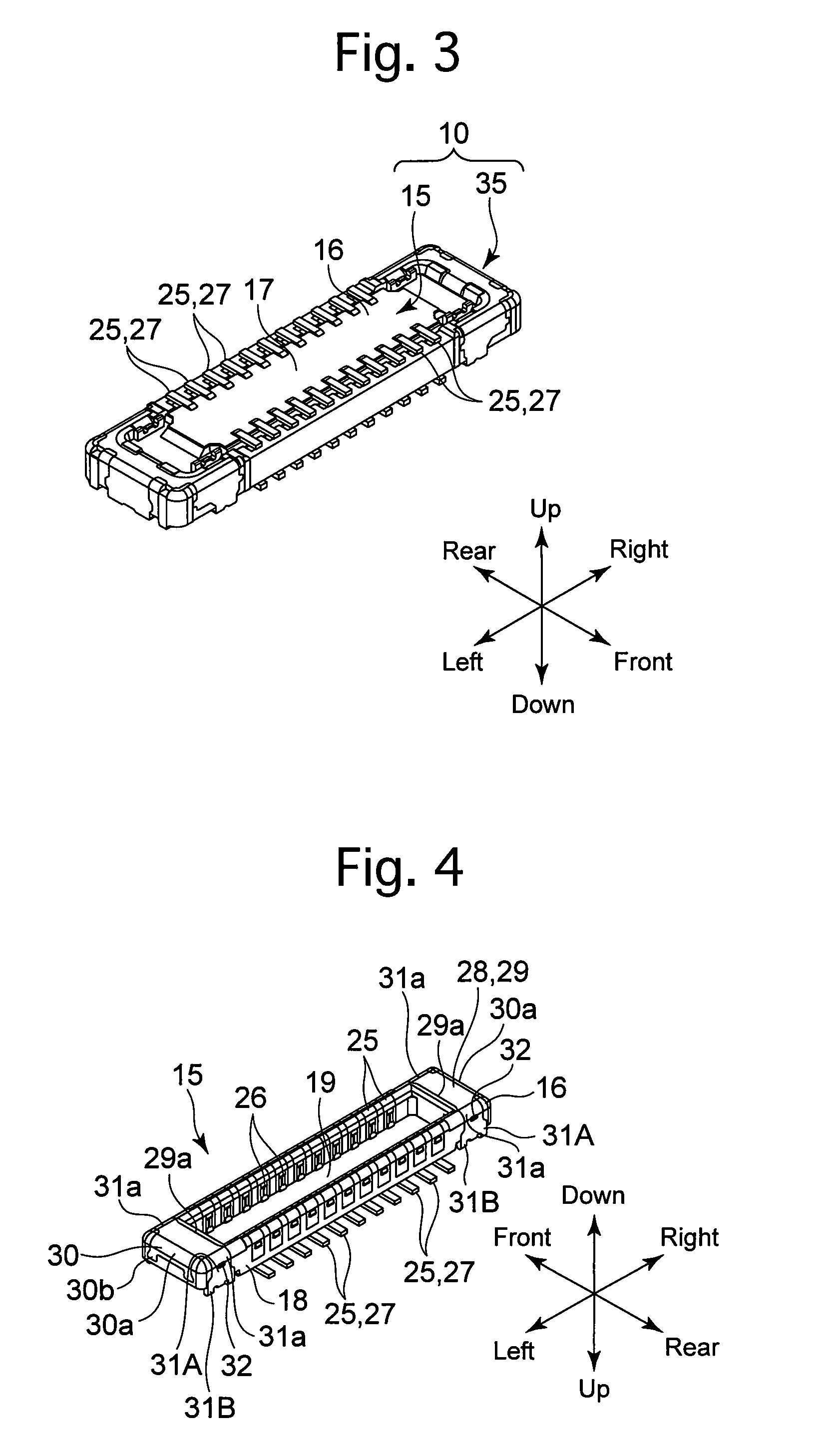
[0049]First, the detailed structure of the plug connector 15 will be hereinafter discussed with reference mainly to FIGS. 4 and 5.

[0050]The plug connector 15 is provided with a plug insulator 16, a plurality of plug contacts (two (front and rear) arrays of plug contacts) 25 and two plug-side metal fixing members 28, which constitute major elements of the plug connector 15. The plug connector 15 is fully integrated by insert molding using forming dies (not shown) for molding the plug con...


PUM

PropertyMeasurementUnit
shapeaaaaaaaaaa
resilientaaaaaaaaaa
electrical continuityaaaaaaaaaa

Abstract

A receptacle connector includes a receptacle insulator having an annular outer peripheral wall which defines a fitting recess; receptacle contacts; and a receptacle-side metal fixing member. When a projecting fitting portion of a plug insulator of a plug connector is fitted into the fitting recess, plug contacts of the plug connector come into contact with the receptacle contacts, and the plug connector comes into contact with the receptacle-side metal fixing member. The receptacle-side metal fixing member and the receptacle insulator are integrally formed by insert molding, and the receptacle-side metal fixing member includes a resilient contact portion which is spaced from a surface of the outer peripheral wall on the circumferentially inner side thereof when the resilient contact portion is in a free state.

Description

CROSS REFERENCE TO RELATED APPLICATION[0001]The present invention is related to and claims priority of the following co-pending application, namely, Japanese Patent Application No. 2013-239003 filed on Nov. 19, 2013.FIELD OF THE INVENTION[0002]The present invention relates to a receptacle connector capable of being connected to and disconnected from a plug connector, and a method of producing such a receptacle connector.BACKGROUND OF THE INVENTION[0003]Electronic apparatuses and electrical apparatuses such as desktop PCs (personal computers), notebook PCs, mobile phones, smart devices (e.g., smartphones) or tablet PCs usually incorporate a circuit board which contains electronic parts and another circuit board which contains other electronic parts.[0004]The connectors disclosed in Japanese Unexamined Patent Publication No. 2013-206771 and Japanese Patent Publication No. 5,250,450 are for connecting such two circuit boards, and are provided with a receptacle connector mounted on a ci...

Claims


Application Information

Patent Timeline
Patent Type & Authority Applications(United States)
IPC IPC(8): H01R12/71H01R43/18H01R24/60
CPCH01R12/716H01R43/18H01R24/60H01R12/7011
Inventor WATANABE, HIROAKI
Owner KYOCERA CORP
Why Eureka
Try Eureka