Systems, articles, and methods for capacitive electromyography sensors

a capacitive electromyography and sensor technology, applied in the field of electromyography, can solve the problems of inconvenient hand encumbrance, intramuscular emg sensor, obvious more invasive, and less desirable from the patient's point of view

Active Publication Date: 2015-05-21
META PLATFORMS TECH LLC
View PDF0 Cites 83 Cited by
  • Summary
  • Abstract
  • Description
  • Claims
  • Application Information

AI Technical Summary

Benefits of technology

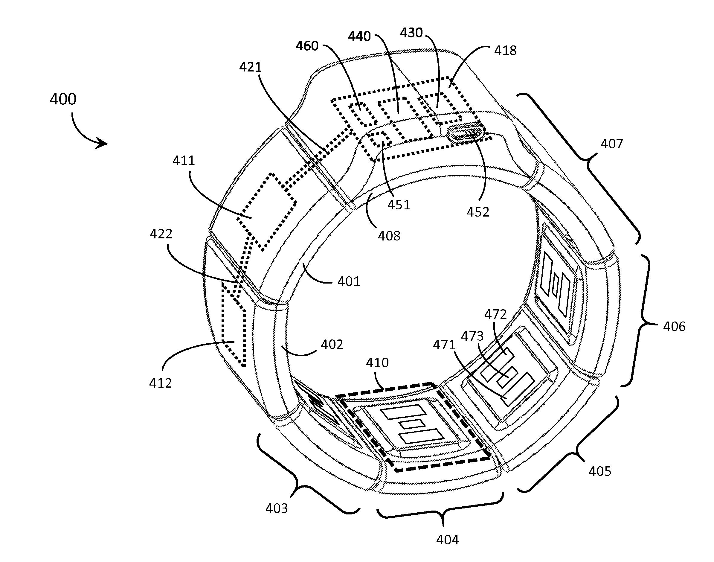
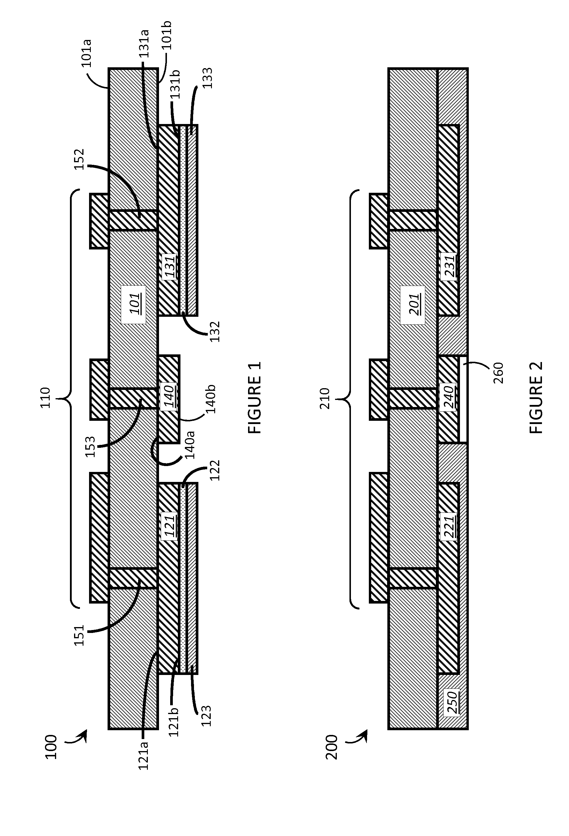
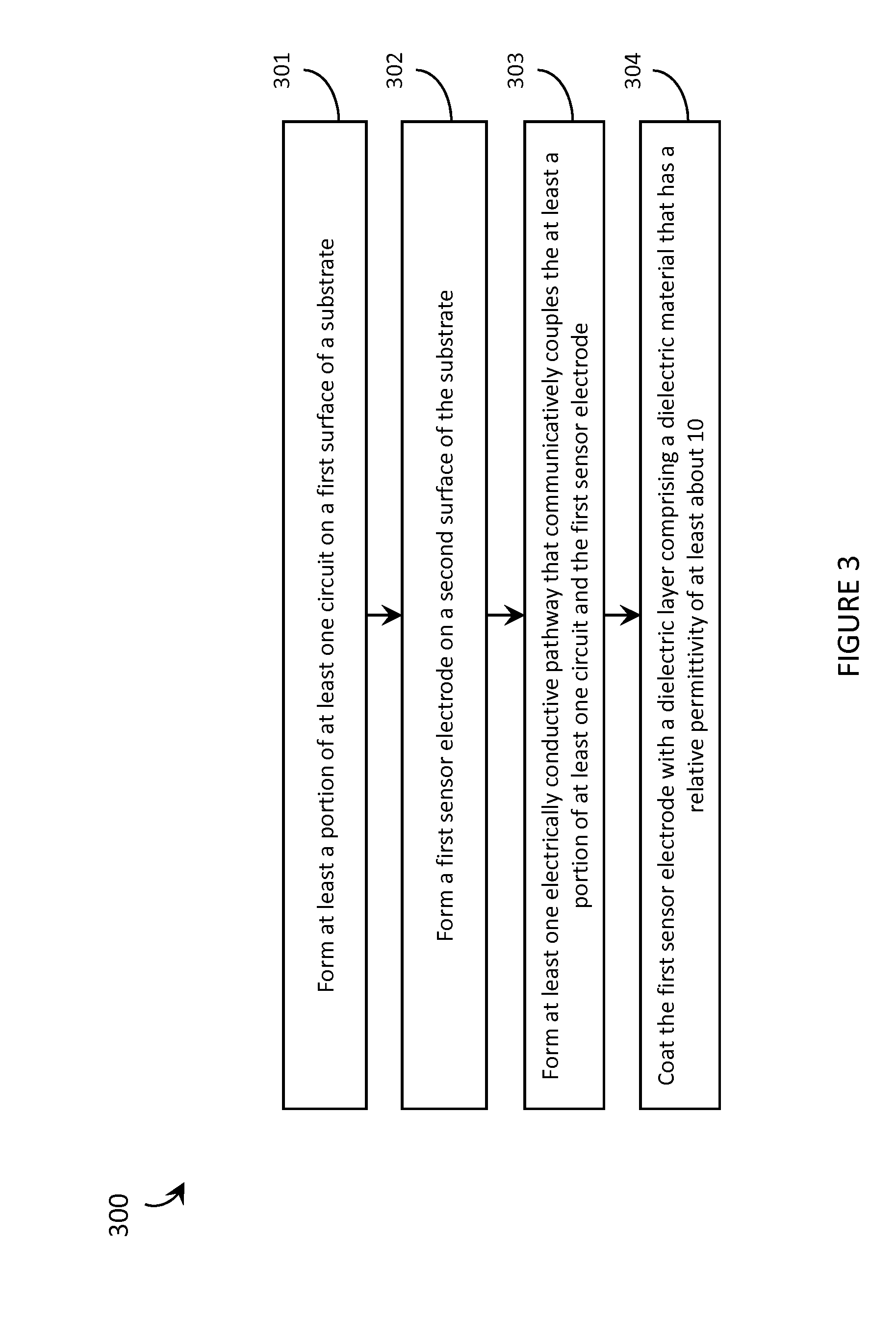
[0012]A capacitive electromyography (“EMG”) sensor may be summarized as including a substrate; a first sensor electrode carried by the substrate, wherein the first sensor electrode comprises an electrically conductive plate having a first surface that faces the substrate and a second surface that is opposite the first surface; circuitry communicatively coupled to the first sensor electrode; and a dielectric layer formed of a dielectric material that has a relative permittivity of at least about 10, wherein the dielectric layer coats the second surface of the first sensor electrode. The first sensor electrode may be formed of a material including copper. The circuitry may include at least one circuit selected from the group consisting of: an amplification circuit, a filtering circuit, and an analog-to-digital conversion circuit. At least a portion of the circuitry may be carried by the substrate. The substrate may include a first surface and a second surface, the second surface opposite the first surface across a thickness of the substrate, and the at least a portion of the circuitry may be carried by the first surface of the substrate and the first sensor electrode may be carried by the second surface of the substrate. The dielectric layer may include a ceramic material. The dielectric layer may include an X7R ceramic material. The substrate, the first sensor electrode, and the dielectric layer may constitute a laminate structure. The capacitive EMG sensor may further include an electrically conductive epoxy sandwiched in between the dielectric layer and the first sensor electrode, wherein the dielectric layer is adhered to the first sensor electrode by the electrically conductive epoxy. Alternatively, the capacitive EMG sensor may further include an electrically conductive solder sandwiched in between the dielectric layer and the first sensor electrode, wherein the dielectric layer is adhered to the first sensor electrode by the electrically conductive solder. The dielectric layer may have a thickness of less than about 10 micrometers. The capacitive EMG sensor may be a differential capacitive EMG sensor that further includes a second sensor electrode carried by the substrate, the second sensor electrode comprising an electrically conductive plate having a first surface that faces the substrate and a second surface that is opposite the first surface across a thickness of the second sensor electrode, wherein the second sensor electrode is communicatively coupled to the circuitry, and wherein the dielectric layer coats the second surface of the second sensor electrode. The dielectric layer may comprise a single continuous layer of dielectric material that coats both the second surface of the first sensor electrode and the second surface of the second sensor electrode. The dielectric layer may comprise a first section that coats the second surface of the first sensor electrode and at least a second section that coats the second surface of the second sensor electrode, wherein the first section of the dielectric layer is physically separate from the second section of the dielectric layer. The first sensor electrode and the second sensor electrode may be substantially coplanar. The capacitive EMG sensor may further include a ground electrode carried by the substrate, the ground electrode comprising an electrically conductive plate having a first surface that faces the substrate and a second surface that is opposite the first surface across a thickness of the ground electrode, wherein the ground electrode is communicatively coupled to the circuitry, and wherein the second surface of the ground electrode is exposed and not coated by the dielectric layer. The capacitive EMG sensor may further include at least one additional layer that is sandwiched in between the first sensor electrode and the substrate.

Problems solved by technology

However, the convenience of being able to carry a portable electronic device has also introduced the inconvenience of having one's hand(s) encumbered by the device itself.
Intramuscular EMG sensor measurements can be much more precise than surface EMG sensor measurements; however, intramuscular EMG sensors must be applied by a trained professional, are obviously more invasive, and are less desirable from the patient's point of view.
The use of intramuscular EMG sensors is generally limited to clinical settings.
This obviously limits the appeal of resistive EMG sensors to users, in particular for home and / or recreational use.
However, capacitive EMG sensors are still very sensitive to moisture and performance can degrade considerably when, for example, a user sweats.

Method used


Image

  • Systems, articles, and methods for capacitive electromyography sensors
  • Systems, articles, and methods for capacitive electromyography sensors
  • Systems, articles, and methods for capacitive electromyography sensors

Examples


Embodiment Construction

[0020]In the following description, certain specific details are set forth in order to provide a thorough understanding of various disclosed embodiments. However, one skilled in the relevant art will recognize that embodiments may be practiced without one or more of these specific details, or with other methods, components, materials, etc. In other instances, well-known structures associated with electric circuits, and in particular printed circuit boards, have not been shown or described in detail to avoid unnecessarily obscuring descriptions of the embodiments.

[0021]Unless the context requires otherwise, throughout the specification and claims which follow, the word “comprise” and variations thereof, such as, “comprises” and “comprising” are to be construed in an open, inclusive sense, that is as “including, but not limited to.”

[0022]Reference throughout this specification to “one embodiment” or “an embodiment” means that a particular feature, structures, or characteristics may be...


PUM


Abstract

Systems, articles, and methods for improved capacitive electromyography (“EMG”) sensors are described. The improved capacitive EMG sensors include one or more sensor electrode(s) that is/are coated with a protective barrier formed of a material that has a relative permittivity ∈r of about 10 or more. The protective barrier shields the sensor electrode(s) from moisture, sweat, skin oils, etc. while advantageously contributing to a large capacitance between the sensor electrode(s) and the user's body. In this way, the improved capacitive EMG sensors provide enhanced robustness against variations in skin and/or environmental conditions. Such improved capacitive EMG sensors are particularly well-suited for use in wearable EMG devices that may be worn by a user for an extended period of time and/or under a variety of skin and/or environmental conditions. A wearable EMG device that provides a component of a human-electronics interface and incorporates such improved capacitive EMG sensors is described.

Description

BACKGROUND[0001]1. Technical Field[0002]The present systems, articles, and methods generally relate to electromyography and particularly relate to capacitive electromyography sensors.[0003]2. Description of the Related ArtWearable Electronic Devices[0004]Electronic devices are commonplace throughout most of the world today. Advancements in integrated circuit technology have enabled the development of electronic devices that are sufficiently small and lightweight to be carried by the user. Such “portable” electronic devices may include on-board power supplies (such as batteries or other power storage systems) and may be designed to operate without any wire-connections to other electronic systems; however, a small and lightweight electronic device may still be considered portable even if it includes a wire-connection to another electronic system. For example, a microphone may be considered a portable electronic device whether it is operated wirelessly or through a wire-connection.[000...

Claims


Application Information

Patent Timeline
Patent Type & Authority Applications(United States)
IPC IPC(8): G06F3/01A61B5/0492A61B5/296
CPCA61B5/0492G06F3/015A61B5/681A61B2562/247G06F1/163G06F3/014A61B5/296
Inventor MORUN, CEZARLAKE, STEPHEN
Owner META PLATFORMS TECH LLC
Why Eureka
Try Eureka