Pneumatically actuated computer input device

a computer input and pneumatic actuator technology, applied in the field of pneumatically actuated computer input devices, can solve the problems of complicated aseptic operation of the room, and achieve the effect of rapid re-initialisation

Active Publication Date: 2015-05-21
K LAFLAMME ERIC
View PDF14 Cites 1 Cited by
  • Summary
  • Abstract
  • Description
  • Claims
  • Application Information

AI Technical Summary

Benefits of technology

[0004]It is a main advantage of this invention to provide for an easy way for a dentist to operate a computer input device such as a mouse or game port device that is used for controlling various devices such as an intra oral camera by simply using a foot pedal which controls the flow of a pneumatic hose. The air pressure presses down on a switch on a computer input device circuit. Pneumatic pedals are well known in the art of dentistry and controlling a switch using air makes it easy for dentists to learn how to

Problems solved by technology

The problem is in how to computer can be made to do an action while the dentist has his hands busy without having to add

Method used


Image

  • Pneumatically actuated computer input device
  • Pneumatically actuated computer input device
  • Pneumatically actuated computer input device

Examples


Embodiment Construction

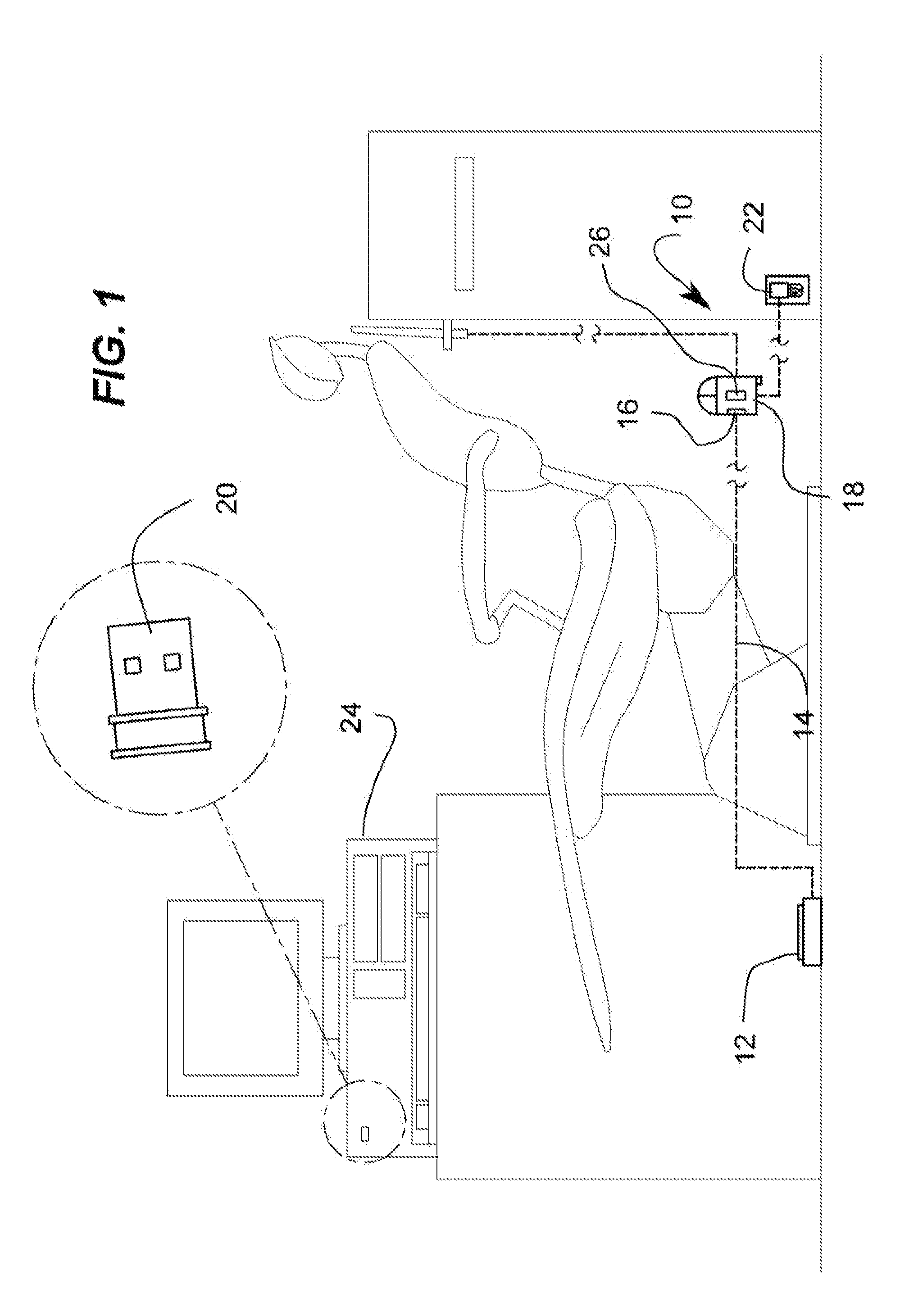
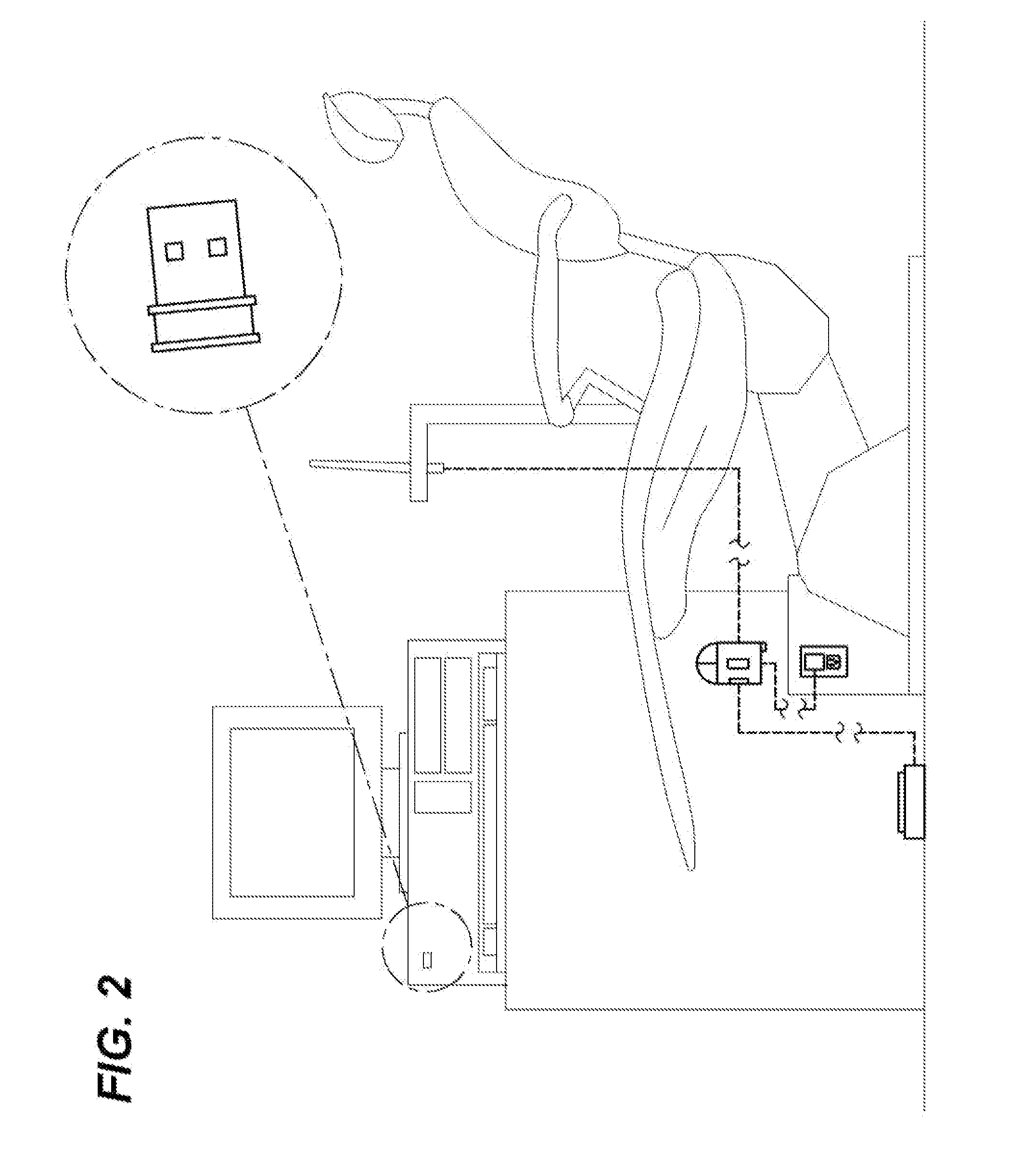
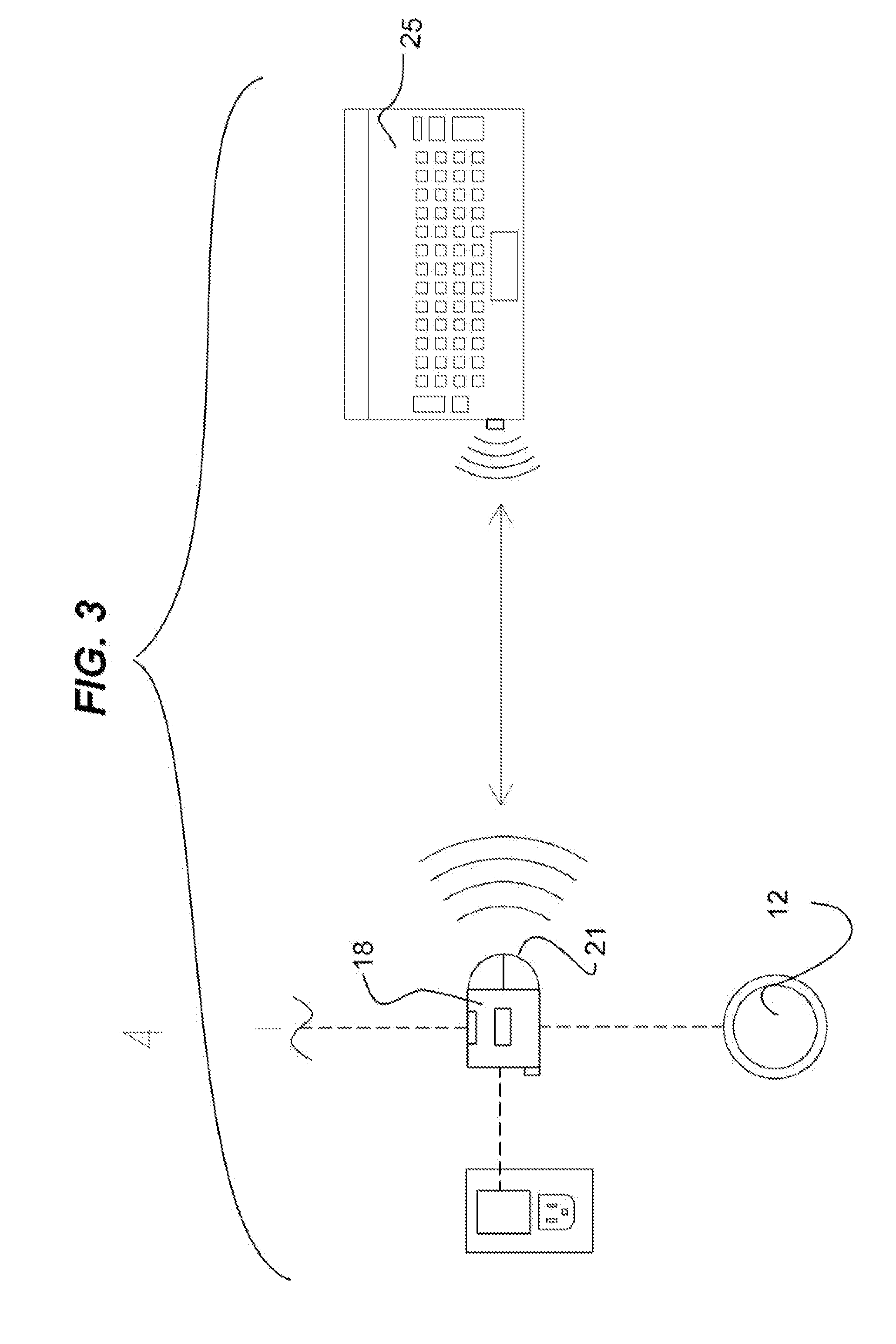
[0024]A pneumatically actuated computer input device (10) is actuated by a foot pedal (12). The foot pedal (12) itself controls the flow of pressurized air inside a pneumatic hose (14). The pressure inflates a pneumatic actuator (16) which then presses down on a switch member (26) located on the input device circuit member (18). Once a click is made (or any combination thereof), the rest works like a usual input device click—including macros—whether the input device circuit (18) is wireless,—in which case a signal receiver (20) connected to a computer (24), or keyboard (25) is required—or wire based (not shown). The input device circuit member (18) is generally connected to a power source such as an AC source (22) for example, or a DC source such as a battery member (26), for example. The input device circuit member (18) also comprises a signal transmitter (21) to communicate with the signal receiver (20).

[0025]FIG. 5 shows a variant, the input device member (18) wherein the pneumat...


PUM


Abstract

A pneumatically actuated computer input device comprises an input device circuit member having a hollow body, at least one switch member within the hollow body adapted to send electronic signals to a computer terminal, and a pneumatic actuator within the hollow body adapted to be inflated and press against and activate the at least one switch member. A pneumatic hose connected at a distal end to the pneumatic actuator and extending outward from the hollow body at a predetermined length and adapted to supply air thereto, and a foot pedal connected to the pneumatic hose at an opposite end from the distal end and adapted to control the air supply through the pneumatic hose and to the pneumatic actuator, such that when the foot pedal is pressed the pneumatic actuator is filled with air, expands, and presses against the at least one switch member which then sends an electronic signal to the computer terminal.

Description

[0001]This application claims priority based on request GB1320238.7 filed Nov. 15, 2013FIELD OF THE INVENTION[0002]The present invention relates generally to computer input interface but more particularly to a pneumatically actuated computer input device.BACKGROUND OF THE INVENTION[0003]Dentists rely increasingly on the use of computers in their practice. It can be for imagery purposes such as taking photos or videos of a patient's mouth, for example. The problem is in how to computer can be made to do an action while the dentist has his hands busy without having to add a second pneumatic or electronic pedal, as each added piece of equipment makes keeping the room aseptic more complicated.SUMMARY OF THE INVENTION[0004]It is a main advantage of this invention to provide for an easy way for a dentist to operate a computer input device such as a mouse or game port device that is used for controlling various devices such as an intra oral camera by simply using a foot pedal which control...

Claims


Application Information

Patent Timeline
IPC IPC(8): G05D7/06G05B15/02
CPCG05B15/02G05D7/0629G06F3/03543A61B1/24G06F3/0334A61B1/00042G06F3/03G05D7/06G05D7/0623G06F3/01
Inventor K-LAFLAMME, ERIC
Owner K LAFLAMME ERIC
Why Eureka
Try Eureka