Disposable cartridge for microfluidics systems
a technology of microfluidics and cartridges, which is applied in the direction of fluid pressure measurement, liquid/fluent solid measurement, peptide measurement, etc., can solve the problem of large-scale systems that are not designed to be portabl
- Summary
- Abstract
- Description
- Claims
- Application Information
AI Technical Summary
Benefits of technology
Problems solved by technology
Method used
Image
Examples
first embodiment
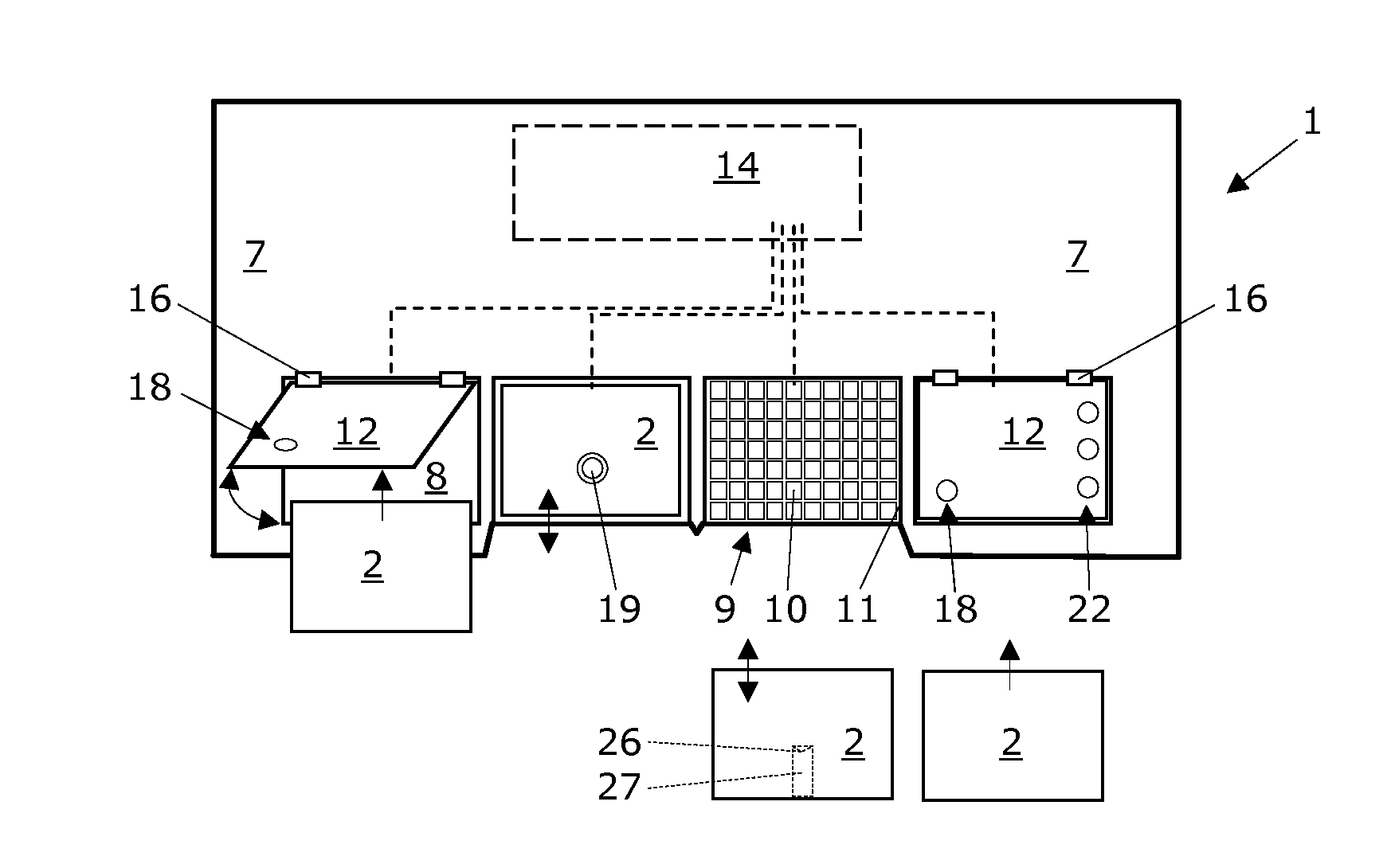
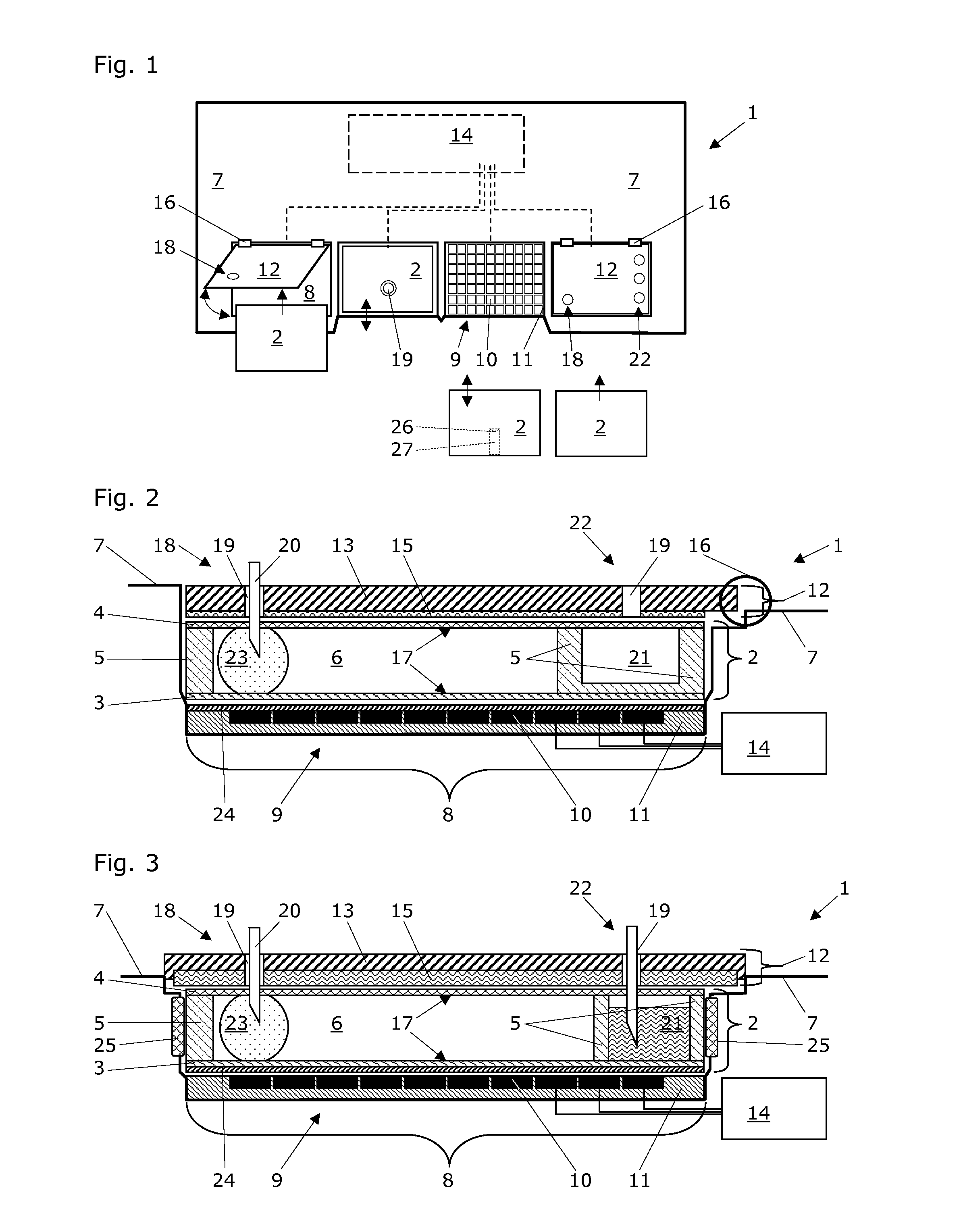
[0091]The FIG. 2 shows a section view of one exemplary cartridge accommodation site 8 with a disposable cartridge 2 accommodated therein. The cover plate 12 is mechanically connected with the base unit 7 of the digital microfluidics system 1 via a hinge 16; thus, the cover plate 12 can swing open and a disposable cartridge 2 can be placed on the cartridge accommodation site 8 via top-entry loading (see FIG. 1). The electrically conductive material 15 of the cover plate 12 is configured as a thin metal plate or metal foil that is attached to the top substrate 13.
[0092]Alternatively, the electrically conductive material 15 of the cover plate 12 is configured as a metal layer that is deposited onto the top substrate 13. Such deposition of the conductive material 15 may be carried out by chemical or physical vapor deposition techniques as they are known per se.
[0093]The cover plate 12 is configured to apply a force to a disposable cartridge 2 that is accommodated at the cartridge accom...
second embodiment
[0096]The FIG. 3 shows a section view of one exemplary cartridge accommodation site 8 with a disposable cartridge 2 accommodated therein. Different to the previous embodiment, the cover plate 12 is mechanically connected with the base unit 7 of the digital microfluidics system 1 and immovably fixed therewith. The electrically conductive material 15 of the cover plate 12 is configured as a thick metal plate that is attached to the top substrate 13. Here, the cover plate 12 is not configured to apply a force to the disposable cartridge 2 that is accommodated at the cartridge accommodation site 8 of the base unit 7; thus, the cover plate 12 stays in place and a disposable cartridge 2 can be placed on the cartridge accommodation site 8 via front-entry loading. Such front-entry loading usually includes a movement of the disposable cartridge 2 in a direction that is parallel to the electrode array 9 (see FIG. 1). In order to enable proper drawing-in of the disposable cartridge 2 and to n...
third embodiment
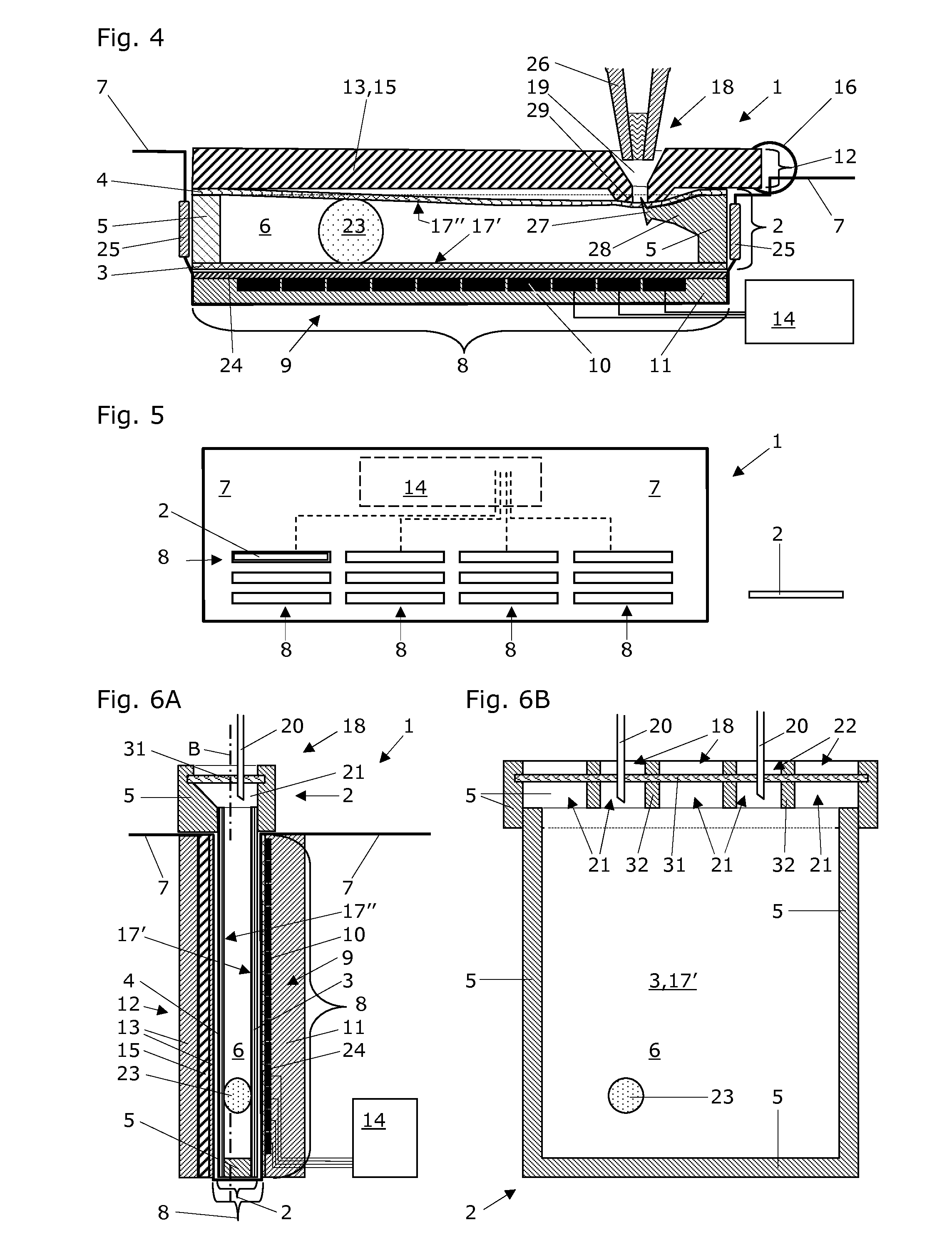
[0100]The FIG. 4 shows a section view of one exemplary cartridge accommodation site 8 with a disposable cartridge 2 accommodated therein. The cover plate 12 is mechanically connected with the base unit 7 of the digital microfluidics system 1 by a hinge 16. In order to enable proper top-loading of the disposable cartridge 2 and to neatly position the cartridge at the accommodation site 8, the base unit 7 preferably is equipped with insertion guides 25. These insertion guides 25 preferably are from a self-lubricating plastic material, such as tetrafluorethylene (PTFE) and preferably leave a space between them that is just sufficient for slidingly inserting the disposable cartridge 2. As a first alternative solution, the electrically conductive material 15 of the cover plate 12 is made of metallic conductive material and comprises both the top substrate 13 and the electrically conductive material 15 as a single integrated part. Alternatively, the electrically conductive material 15 of...
PUM
| Property | Measurement | Unit |
|---|---|---|
| size | aaaaa | aaaaa |
| gap width | aaaaa | aaaaa |
| temperature | aaaaa | aaaaa |
Abstract
Description
Claims
Application Information
 - R&D
- Intellectual Property
- Life Sciences
- Materials
- Tech Scout
- Unparalleled Data Quality
- Higher Quality Content
- 60% Fewer Hallucinations
Browse by: Latest US Patents, China's latest patents, Technical Efficacy Thesaurus, Application Domain, Technology Topic, Popular Technical Reports.
© 2025 PatSnap. All rights reserved.Legal|Privacy policy|Modern Slavery Act Transparency Statement|Sitemap|About US| Contact US: help@patsnap.com


