Device and method for tracking maximum power

Inactive Publication Date: 2015-05-28
ELECTRONICS & TELECOMM RES INST
View PDF4 Cites 2 Cited by
  • Summary
  • Abstract
  • Description
  • Claims
  • Application Information

AI Technical Summary

Benefits of technology

[0007]The present invention provides a maximum power tracking device

Problems solved by technology

Especially, the intensity of solar light, that is, an external environment factor, cannot be changed artificially.
Also, the angle of solar light may be adjusted by changing the direction of a solar battery, but changing the direction requires high power consump

Method used


Image

  • Device and method for tracking maximum power
  • Device and method for tracking maximum power
  • Device and method for tracking maximum power

Examples


Example

[0027]The present invention may apply various modifications and thus have diverse embodiments. Therefore, specific embodiments are shown in the drawings and described in more detail. Thus, it is intended that the present invention covers the modifications and variations of this invention provided they come within the scope of the appended claims and their equivalents.

[0028]Like reference numerals refer to like elements throughout. Also, in the figures, the dimensions of layers and regions are exaggerated for clarity of illustration. Although terms like first and second may be used to describe various components, the components are not limited to the terms. These terms are used only to distinguish one component from other components. For example, a first component may be referred to as a second component and vice versa without being departing from the scope of the present invention. The terms of a singular form may include plural forms unless they have a clearly different meaning in ...


PUM


Abstract

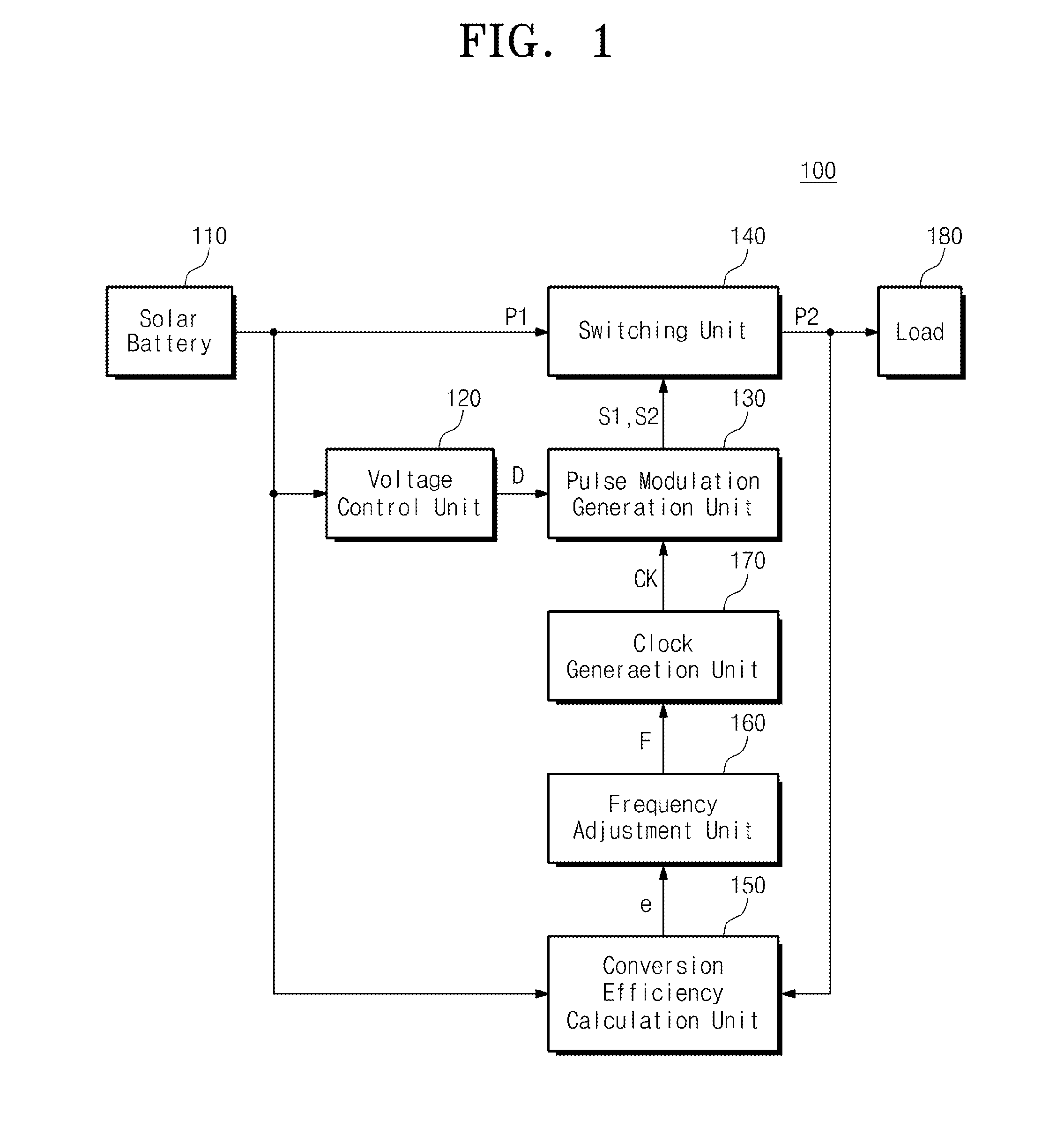
Provided is a maximum power tracking device. The device includes: a battery outputting a first power; a switching unit changing the first power into a second power in response to a switching control signal; and a pulse modulation generation unit adjusting a pulse width of the switching control signal on the basis of the first power and adjusting a frequency of the switching control signal on the basis of the first power and the second power.

Description

CROSS-REFERENCE TO RELATED APPLICATIONS[0001]This U.S. non-provisional patent application claims priority under 35 U.S.C. §119 of Korean Patent Application No. 10-2013-0145346, filed on Nov. 27, 2013, the entire contents of which are hereby incorporated by reference.BACKGROUND OF THE INVENTION[0002]The present invention disclosed herein relates to a maximum power tacking device, and more particularly, to a maximum power tracking device and method maximizing the conversion efficiency of a DC-DC converter.[0003]Recently, various developments on solar battery generating the most power among new regeneration energies are being made. Among them, various developments on solar battery collecting solar energy and converting it into electrical energy have been made.[0004]In relation to a solar battery, the amount of energy varies depending on the intensity of solar light or the angle of light. Especially, the intensity of solar light, that is, an external environment factor, cannot be change...

Claims


Application Information

Patent Timeline
IPC IPC(8): H02M3/158
CPCH02M3/158G05F1/67H02M1/0054Y02B70/10Y02E10/50H02S40/30
Inventor HEO, SEWANYANG, YIL SUK
Owner ELECTRONICS & TELECOMM RES INST
Why Eureka
Try Eureka