Chlorine dioxide generation

a technology of chlorine dioxide and ac reaction chamber, which is applied in the direction of chlorine oxides, liquid-liquid reaction processes, chemical/physical/physicochemical processes, etc., can solve the problems of increased operational hazards, clo2 concentration in the ac reaction chamber can greatly exceed this value, and achieve the effect of facilitating safe clo2 generation

Active Publication Date: 2018-07-05
INT DIOXCIDE
View PDF0 Cites 2 Cited by
  • Summary
  • Abstract
  • Description
  • Claims
  • Application Information

AI Technical Summary

Benefits of technology

[0008]The ClO2 generator design combined with the utility of a float-dependent valve described herein is novel and has not been previously. Additionally, the inverted orientation of the floating ball check valve versus how it is typically deployed is non-obvious and is a unique approach to a novel reactor design. Instead of serving as a check valve, it is a safety relief valve during normal operations whereby it remains closed during normal operation but will open in case of elevated pressure in the reaction chamber. Also, it serves as a safety interlock during start-up by ensuring proper dilution water is present in the flow chamber before chemical production initiates. The float-dependent valve, being an isolated mechanical device, does not require any wiring or connection to secondary equipment or sensors to perform these functions. The float-dependent check valve will only close and allow chemical flows to commence when there is both a proper amount of dilution water in the flow chamber and a vacuum is being pulled over the reaction chamber. There is no other ClO2 generator that has been designed with such a simple and elegant safety interlock that serves to facilitate safe ClO2 generation despite utilizing reactor zones that contain higher than 3,000 ppm ClO2.

Problems solved by technology

Therefore, ClO2 cannot be shipped and must be prepared on site.
However, ClO2 concentration in the AC reaction chamber can greatly exceed this value, especially when acid is fed near stoichiometric ratio to chlorite and the reactor is not purged when the system is turned off.
Larger ClO2 generation capacity requires proportionately larger reaction chamber volumes, leading to increased operational hazards.
Thus, AC systems are generally limited to lower production levels, such as 50 lb / day ClO2 or lower.
In some cases, the reaction chamber is situated fully or partially within the process flow stream, but these systems often do not have mechanisms to prevent ClO2 generation in the event of low to no process flow, or to respond to a high-pressure event in the reaction chamber.
Due to the desire for low-cost systems, the AC generator systems generally have minimal safety interlocks and limited ClO2 generation capacity.
While these float sensors may offer a way to ensure there is a proper amount of dilution water before chemical addition and preventing overflow of a basin, there is no safety mechanism attributed to the reaction chamber itself, which is where destructive failures can be the most severe due to the presence of high concentration of ClO2.

Method used


Image

  • Chlorine dioxide generation
  • Chlorine dioxide generation
  • Chlorine dioxide generation

Examples


example 1

Process Flow Interruption

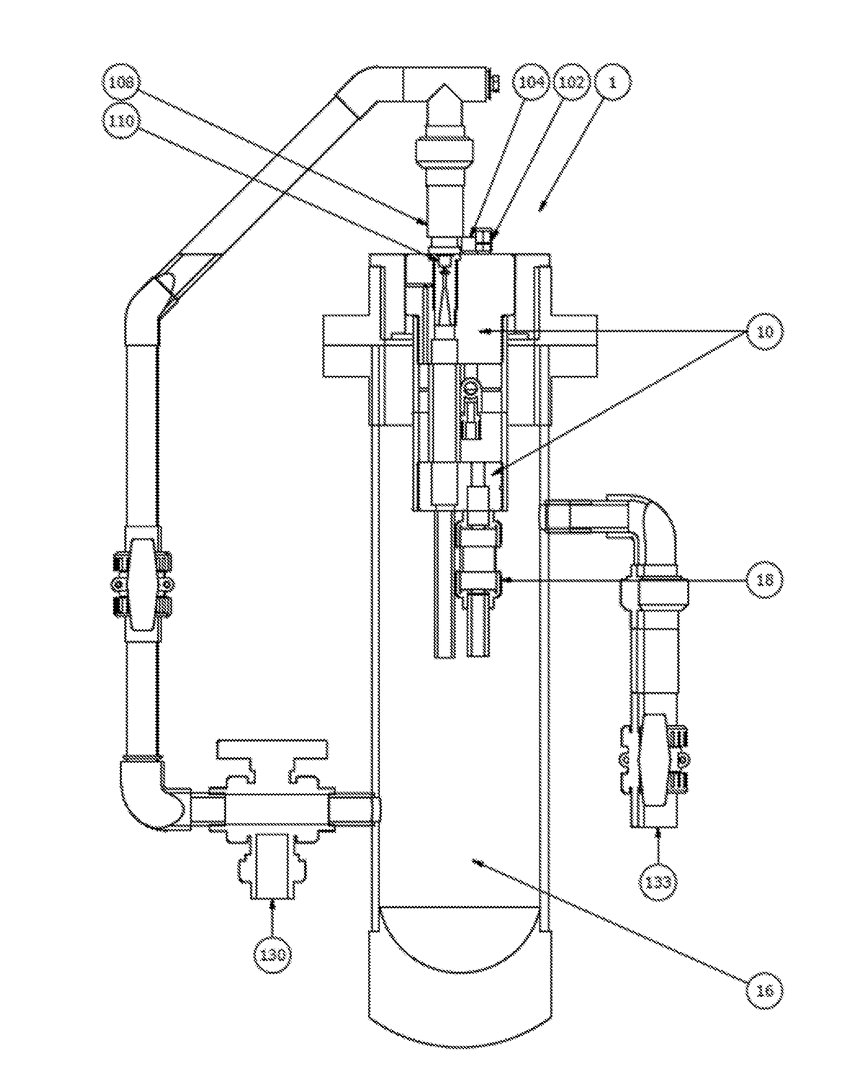
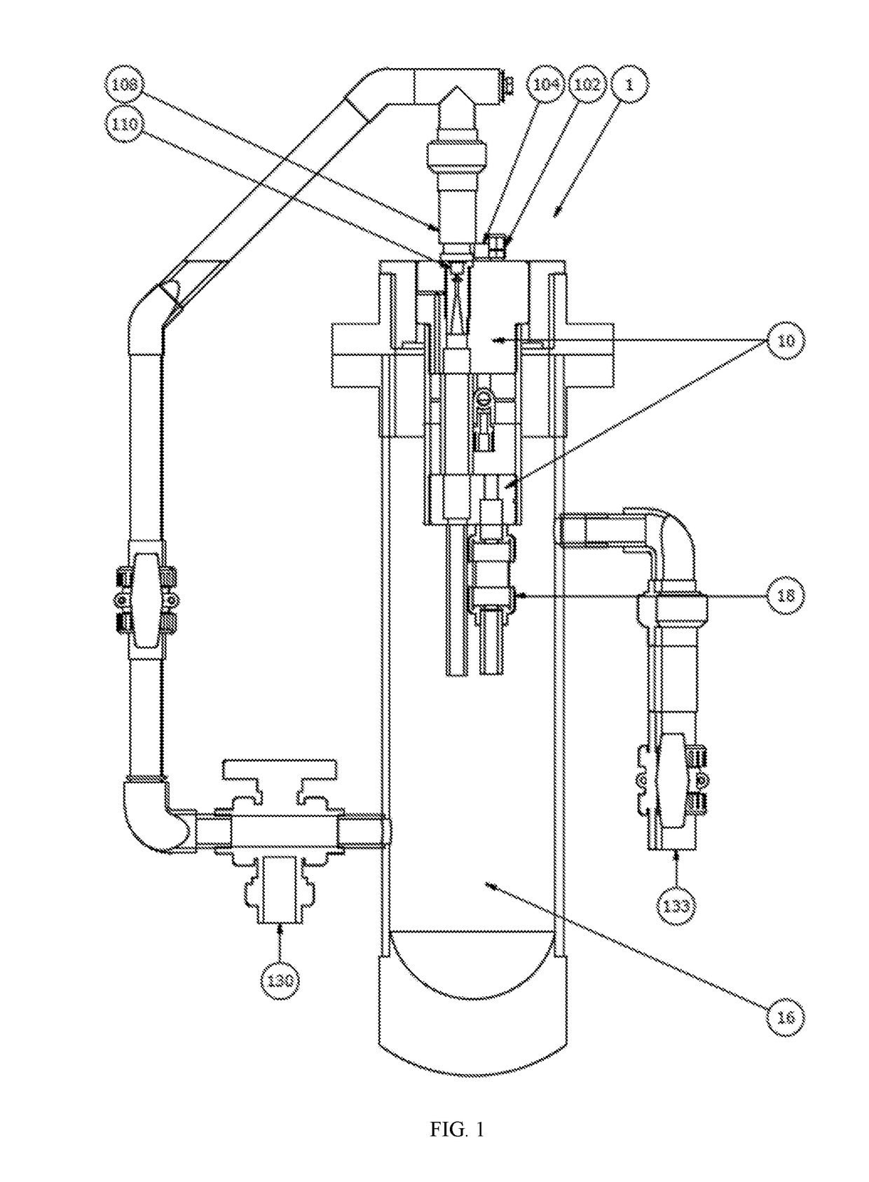
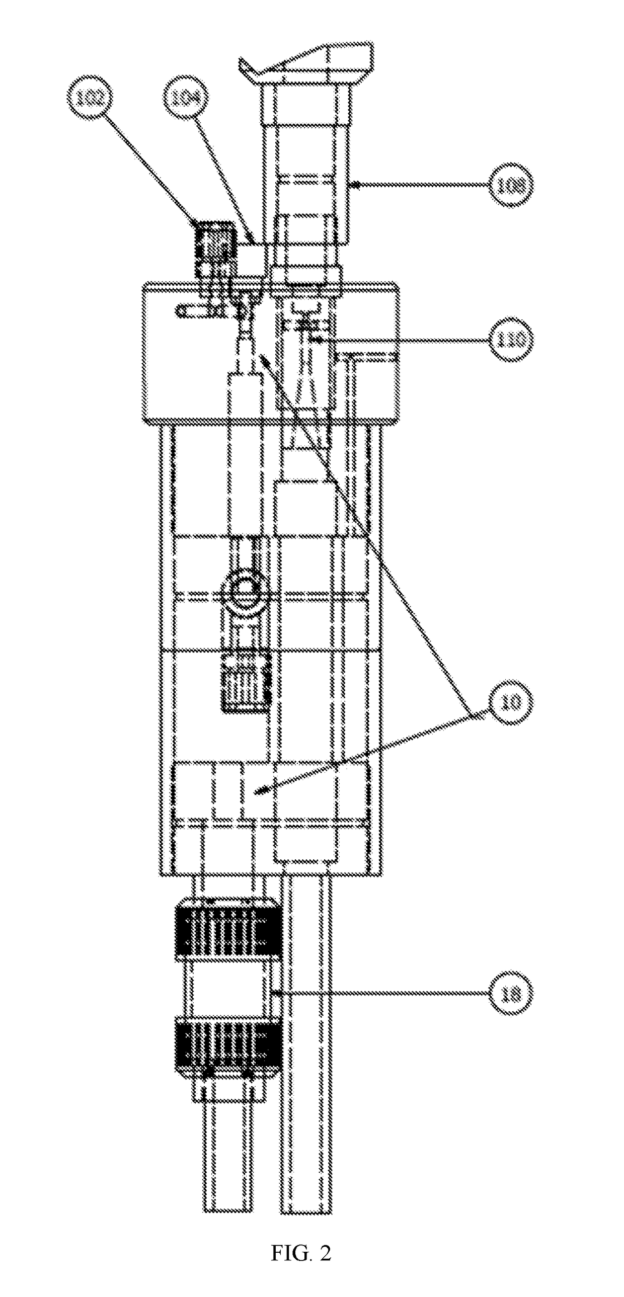
[0031]After the device had produced ClO2 for 30 minutes, the process water was turned off to simulate a system that was shut down before it had time to be purged or emptied. With the process flow supply interrupted, the flow to the eductor was also interrupted, and the vacuum on the reaction chamber halted. At this point, the float-dependent valve 18 opened and allowed the contents of the reaction chamber to slowly drain into the flow chamber. This safety measure minimizes the risk of ClO2 vapors building up in an enclosed reaction chamber volume.

example 2

Low Acid Flow and Extended Dwell Time

[0032]In a more extreme set of circumstances, the acid feed was lowered to simulate a system that had not been properly configured to correct precursor feed ratios. When the acid feed is low, the ClO2 concentration within the reaction chamber can be considerably higher if there is sufficient dwell time to convert the chlorite to ClO2. In a shutdown scenario, the ClO2 can continue to form over time after shutdown. Under these conditions, the float-dependent valve 18 sufficiently drained and diluted the reaction chamber 10 contents into the flow chamber 16 before any decomposition events occurred.

example 3

Pressure Event Within the Reaction Chamber

[0033]A test was conducted in which water was forced through the acid feed at a rate of 310 gallons per day (GPD) while the pressure of the reaction chamber was monitored. With the float-dependent valve 18 in place, the maximum pressure achieved in the flow chamber was 1.2 psig. The check valve was then replaced by a plug to prevent venting, and the test was repeated. Applying the same flow rate of 310 GPD, the reaction chamber pressure increased to 4.4 psig, which is a nearly 4 times greater pressure differential between the reaction chamber 10 and the flow chamber 16. In these tests, the flow chamber 16 was being emptied to an open container, and did not have significant back pressure.

[0034]The iteration without the float-dependent valve 18 is similar to traditionally constructed AC ClO2 generators, in which the reaction chamber consists of only two feed inlets and a single outlet being diluted into a process water supply. Therefore, in th...


PUM

PropertyMeasurementUnit
vacuumaaaaaaaaaa
concentrationaaaaaaaaaa
pressureaaaaaaaaaa

Abstract

Devices and methods for safely using acid/chlorite ClO2 generator chemistry for water treatment, whereby a valve prevents chemical draw unless there is both vacuum within the reaction chamber as well as suitable water volume in the flow chamber for dilution, are described. The float-dependent valve can also allow for direct venting from the reaction chamber to the flow chamber in the event of elevated pressure in the reaction chamber. This approach delivers an inherently safer ClO2 generator design for systems that utilize high strength reactor zones with ClO2 concentration above 3,000 ppm.

Description

CROSS-REFERENCE TO RELATED APPLICATIONS[0001]This application is a continuation application claiming priority to and benefit of U.S. Non-Provisional application Ser. No. 15 / 394,885 filed Dec. 30, 2016, entitled “Chlorine Dioxide Generation,” which is hereby incorporated herein by reference in its entirety. (A Petition to Convert the above referenced Ser. No. to a provisional application is pending with the United States Patent and Trademark Office. In the event said Petition is granted, the priority claim will be corrected accordingly.)BACKGROUND OF THE INVENTION[0002]Chlorine dioxide (ClO2) is a potent oxidizing agent that is commonly used as a water treatment disinfectant. In the vapor phase, gaseous ClO2 ignites at concentrations greater than 10% by volume. Therefore, ClO2 cannot be shipped and must be prepared on site. Aqueous solutions of ClO2 generated at the point of use can be safely handled and applied as long as conditions that may lead to decomposition do not develop.[000...

Claims


Application Information

Patent Timeline
Patent Type & Authority Applications(United States)
IPC IPC(8): C01B11/02B01J19/00
CPCB01J2219/00763B01J2219/24B01J2219/00182C01B11/024B01J19/006C01B11/022B01J19/002B01J7/02B01J14/00B01J19/0073B01J2219/0027
Inventor ANDRE, NEILBELISLE, AIMEE E.BELISLE, RANDY D.HULSMAN, WILLIAM J.
Owner INT DIOXCIDE
Why Eureka
Try Eureka