3D corrected imaging

a technology of 3d correction and imaging, applied in the field of 3d correction imaging, can solve the problems of limited information to be used in the correction of defects of images, limited image acquisition and post-processing, and additional information

Active Publication Date: 2015-05-28
CHILDRENS NAT MEDICAL CENT
View PDF14 Cites 78 Cited by
  • Summary
  • Abstract
  • Description
  • Claims
  • Application Information

AI Technical Summary

Benefits of technology

[0006]With information about the geometry being imaged, one may be able to infer more about the underlying physical processes behind the more complex image distortions, and subsequently correct images to show the underlying objects most clearly. With the ability to sense depth, an optical imager can determine much more about its environment. This knowledge, combined with knowledge of the camera and light source used in a scene, opens new possibilities for post-acquisition image correction.

Problems solved by technology
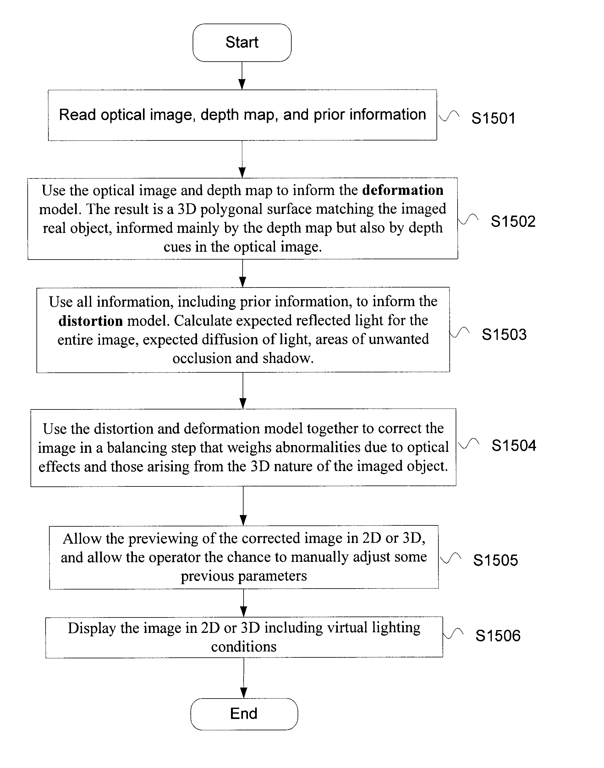
Image acquisition and post-processing are currently limited by the knowledge level of the user.
Once captured, images have limited information to be used in correcting their defects.
The lack of additional information makes correcting complex artifacts and abnormalities in images difficult.
Those image artifacts resulting from specular reflection, shadows, occlusion and other physical phenomenon are not able to be suitably corrected based on the information in a single camera image.
But distance between the imaged object and light source is much harder to estimate.
Often, experts are not completely sure about the underlying physical explanations for perceived abnormalities or features observed in acquired images.
Optically acquired images, however, still suffer from a lack of depth information and sensitivity to distortion, as well as image artifacts and reflections.

Method used


Image

  • 3D corrected imaging
  • 3D corrected imaging
  • 3D corrected imaging

Examples


Embodiment Construction

[0032]In the drawings, like reference numerals designate identical or corresponding parts throughout the several views. Further, as used herein, the words “a”, “an” and the like generally carry a meaning of “one or more”, unless stated otherwise. The drawings are generally drawn to scale unless specified otherwise or illustrating schematic structures or flowcharts.

[0033]Furthermore, the terms “approximately,”“proximate,”“minor,” and similar terms generally refer to ranges that include the identified value within a margin of 20%, 10%, 5% or greater than 0%, and any values therebetween.

[0034]Without limitation, the majority of the systems described herein are directed to the acquisition and analysis of medical images. As required, embodiments of medical imaging systems are disclosed herein. However, the disclosed embodiments are merely exemplary, and it should be understood that the disclosure may be embodied in many various and alternative forms. The systems and methods described her...


PUM


Abstract

A system and method for corrected imaging including an optical camera that captures at least one optical image of an area of interest, a depth sensor that captures at least one depth map of the area of interest, and circuitry that correlates depth information of the at least one depth map to the at least one optical image to generate a depth image, corrects the at least one optical image by applying a model to address alteration in the respective at least one optical image, the model using information from the depth image, and outputs the corrected at least one optical image for display in 2D and/or as a 3D surface.

Description

CROSS REFERENCE TO RELATED APPLICATIONS[0001]This disclosure claims the benefit of U.S. Provisional Application No. 61 / 909,604, filed on Nov. 27, 2013, the disclosure of which is incorporated herein by reference in its entirety.BACKGROUND[0002]1. Field of the Invention[0003]The present embodiments are directed to a system and method of correcting undesirable abnormalities in acquired images through the use of 3-dimensional information and a distortion model.[0004]2. Description of the Related Art[0005]Image acquisition and post-processing are currently limited by the knowledge level of the user. Once captured, images have limited information to be used in correcting their defects. Some automated processing algorithms exist with defined goals that often misrepresent the underlying information. For example, the ‘quick fix’ touch up steps being developed by photo-sharing websites may change the saturation, gain, sharpness and other characteristics to make the resulting images more plea...

Claims


Application Information

Patent Timeline
Patent Type & Authority Applications(United States)
IPC IPC(8): H04N13/02G06T7/00H04N13/122
CPCH04N13/0246G06T7/0051H04N13/0271H04N13/0239H04N2013/0074G06T17/20G06T2207/10004G06T2207/10024G06T2207/10052G06T2207/20221A61B1/00193A61B5/1079A61B2090/367A61B5/0075A61B5/0077A61B2576/00G06T7/337A61B2034/2055H04N13/254H04N13/239H04N13/271H04N13/204G16H30/40H04N13/122A61B1/00194
Inventor KRIEGER, ALEXKIM, PETER C. W.DECKER, RYANSHADEMAN, AZAD
Owner CHILDRENS NAT MEDICAL CENT
Why Eureka
Try Eureka